hexagon logo

Alignment of Gear part

Daer all,

I am new guy for this user forum, currently I am using PC-DMIS in Camio 8.3. (Nikon Make)
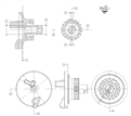
Recently, I found a problem with a alignment issue for my product. It is about a alignment of [A-B I C I D-E ] of part. Please refer to attached file for details. In that A & B are the circles through which we are going to construct a 3S line as a primary datum, then moving ahead C is plane as a secondary datum and lastly D & E are tooth width, from which we need to construct a line through theirs mid points. As in that I don't understand how to do alignment of this part ?
Because there are 2 lines and 1 plane. and mostly unluckily axis of 3D line and Plane is same. Its conflicts my alignment. CAMIO is not allowing to add 2 line 1 plane alignment anyway.

Any help would be greatly appreciated.


Thank you in advance. Slight smile

Best Regards,​​​​​​​
Atul N

Attached Files
Parents
  • Not a rule as far as I was aware.

    A lot of people take it to mean 3 points (plane) 2 points (line) 1 point (point) but was told it actually refers to number of degrees of freedom locked.

    But this in itself is rubbish as I'd consider aligning to a cylinder as the primary datum as a 3-2-1 type alignment, even though leveling and setting origin on a cylinder locks 4 dof.


Reply
  • Not a rule as far as I was aware.

    A lot of people take it to mean 3 points (plane) 2 points (line) 1 point (point) but was told it actually refers to number of degrees of freedom locked.

    But this in itself is rubbish as I'd consider aligning to a cylinder as the primary datum as a 3-2-1 type alignment, even though leveling and setting origin on a cylinder locks 4 dof.


Children
No Data