hexagon logo

Distance between 2 concentric cirlces

Good morning all,

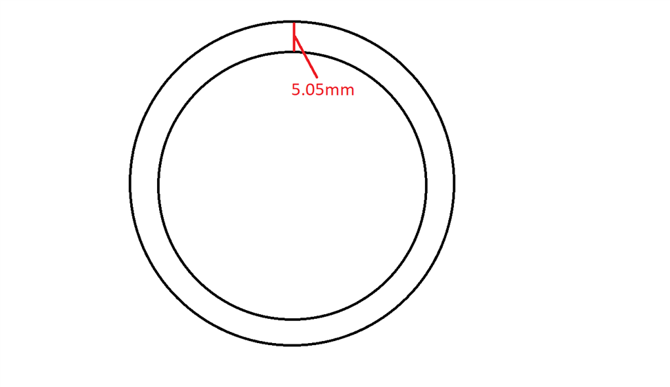
I am having a bit of an issue trying to measure 2 concentric circles and get the distance between the two. No matter what work plane or measurement strategy, I cannot get the measurement I am looking for. I have attached a simple drawing of what exactly I am trying to do. Even in an offline environment straight from the CAD, I am not getting the 5.05 I am looking for. What I am currently doing to get this measurement is taking a a point at X-0 on both circles and calling the distance that way. The issue with that is we have a very small tolerance (-0, +0.05mm) and I am not getting repeatable results using this method. If anyone here as some insight on what I might be doing incorrectly that would be fantastic!

Thanks!
  • Measure 2 circles, make a generic circle, use CIR1.R-CIR2.R as the size for the generic circle.
  • Assuming your picture is looking down the Z axis, create an alignment that origins X & Y on the inner circle. Next add four constructed alignment lines. These will be set to whatever workplane you are in so you need to edit each one so that one is in the XPLUS direction, one is XMINUS, one is YPLUS and the other is YMINUS (see below)

    LIN2 =FEAT/LINE,CARTESIAN,UNBOUNDED,NO
    THEO/<0,0,-0.5>,<0,0,1>
    ACTL/<0,0,-0.5>,<0,0,1>
    CONSTR/LINE,ALIGN,1,WORKPLANE   [COLOR=#e74c3c]<---- toggle the workplane of each line to read XPLUS, XMINUS, YPLUS, YMINUS respectively.[/COLOR]


    Finally construct pierce points between each of your lines and each circle so that you end up with 8 points in total - 4 sets of two points at north, south east & west positions. Set the workplane to ZPLUS and dimension the distance between each set of points. This method will allow for any concentricity error between the two circles whereas the method given by assumes they are perfectly concentric and gives a single value.
  • Measure both circles with the same number of hits and the same direction, at the same height.
    Then calculate the 2D distance between hits.
    Here, it could depends on the workplane :
    ASSIGN/V1=SQRT(DOT(CIRC1.HIT[1..CIRC1.NUMHITS].XYZ-CIRC1.XYZ,CIRC1.HIT[1..CIRC1.NUMHITS].XYZ-CIRC1.XYZ))
    ASSIGN/V2=SQRT(DOT(CIRC2.HIT[1..CIRC2.NUMHITS].XYZ-CIRC2.XYZ,CIRC2.HIT[1..CIRC2.NUMHITS].XYZ-CIRC2.XYZ))
    ASSIGN/DIST_CIRC=ABS(V2-V1)
    If there are at two different heights, then :
    ASSIGN/V1=(CIRC1.HIT[1..CIRC1.NUMHITS].XYZ-CIRC1.XYZ)*MPOINT(1,1,0) if Z work plane
    ASSIGN/V2=(CIRC2.HIT[1..CIRC2.NUMHITS].XYZ-CIRC2.XYZ)*MPOINT(1,1,0)
    ASSIGN/DIST_CIRC=ABS(SQRT(DOT(V1,V1))-SQRT(DOT(V2,V2)))

    Then use arrays as you want (average, min, max...) and dimensin it with a comment / report.
  • This is my go to for checking the thickness of a tube.
    It isnt quite the same as checking the thickness with a pair of pin mics or something because it is just using the diameters to calculate the thickness. For a tight tolerance you might want to use method or just take a point on the inside and one in the exact same locations on the outside and do a 3d distance to them in various locations

    CIR1 =FEAT/CONTACT/CIRCLE/DEFAULT,CARTESIAN,IN,LEAST_SQR
    THEO/<0,0,0>,<0,0,1>, 7.35
    ACTL/<0,0,0>,<0,0,1>,7.35
    TARG/<0,0,0>,<0,0,1>
    START ANG=0,END ANG=360
    ANGLE VEC=<1,0,0>
    DIRECTION=CCW
    SHOW FEATURE PARAMETERS=NO
    SHOW CONTACT PARAMETERS=NO
    CIR2 =FEAT/CONTACT/CIRCLE/DEFAULT,CARTESIAN,IN,LEAST_SQR
    THEO/<0,0,0>,<0,0,1>, 6.35
    ACTL/<0,0,0>,<0,0,1>,6.35
    TARG/<0,0,0>,<0,0,1>
    START ANG=0,END ANG=360
    ANGLE VEC=<1,0,0>
    DIRECTION=CCW
    SHOW FEATURE PARAMETERS=NO
    SHOW CONTACT PARAMETERS=NO
    ASSIGN/ V1= (CIR1.D.MEAS-CIR2.D.MEAS)/2
    F1 =GENERIC/LINE,DEPENDENT,CARTESIAN,$
    NOM/XYZ,<0,0,0>,$
    MEAS/XYZ,<0,0,0>,$
    NOM/IJK,<0,0,1>,$
    MEAS/IJK,<0,0,1>,$
    DISTANCE/ V1,V1
    DIM LOC1= LOCATION OF LINE F1 UNITS=IN ,$
    GRAPH=OFF TEXT=OFF MULT=10.00 OUTPUT=BOTH HALF ANGLE=NO
    AX NOMINAL MEAS +TOL -TOL DEV OUTTOL
    L 0.5000 0.5000 0.2000 0.2000 0.0000 0.0000 ----#----
    END OF DIMENSION LOC1
  • Hey man, thank you so much for this! I've been searching these forums for almost two weeks trying to figure out how to measure an O-Ring depth. This has been the only answer that actually worked for me!
  • how do you use "cir1.r-cir2.r" for the size for the generic circle?
  • use an assignment assing/V1=cir1.r-cir2.r Then create a generic feature using V1.