hexagon logo

Can I loop this?

Hi guys!

I'm on my last week before 4 weeks vacation and I feel great! Sunglasses

I've got this part that I'll be programming, and it's really something...
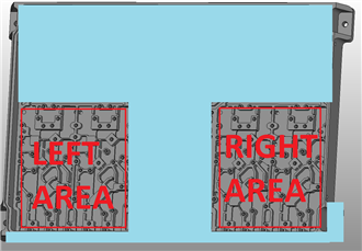
Not that complicated but it's large and it's got a whole bunch of small planes and edges inside, and the drawing states "Profile of any surface 0.8 ABC" (mm),
so I'll have to place points everywhere. It's kind of divided i two halves where the pattern is the same on the left vs right side. (Unfortunately I can't disclose the drawing document.)

So here's my question:
Can I use a loop to program left side, then move it to the right side and get all the points there too?

And would this work?


V1 = LOOP/START, ID = YES, NUMBER = 2, START =1, SKIP =,
OFFSET: XAXIS = 0, YAXIS = 208.82, ZAXIS = 0, ANGLE = 0

[Place all my points here]

LOOP/END


And will all the points be getting unique element names, will I be able to see the second set of points on the CAD-model?

Have a great day everyone! Frog
  • Without seeing a sketch or a better description we can't say, however this is where Pattern/Paste with pattern is usually the best option.

    That loop will simply offset each point by 208.82. Assuming the points all have a 0,0,1 vector that might do it (again, depending on the shape of the part and the arrangement of the points). The points will be 'available' but won't have new ID's, instaed you'll have Pnt1[1] and Pnt1[2],, Pnt2[1] and Pnt2[2] etc.

    With Pattern has a mirror option (need to make sure your origin is in the centre of the part) which will give you individual points.

  • Thank you for the input! Slight smile

    Ok, here's how this part looks and as you can see the left and right area are the same, and not mirrored.
    If Pattern/Paste with pattern is a better option then I'll do that instead.

    I will be using the A0B0 probe angle through all points (and circles) in these areas.
    There will be no need to use the mirror option so I guess I can place the origin near the corner of the part where REF B intersects with REF C?

    I can live with ID's such as Pnt1[1] and Pnt1[2], as long as I can reach them in evaluations.
    But instead of Pnt1[1] and Pnt1[2], could I have Pnt1[L] and Pnt1[R]?


    Attached Files
  • I did something similar a few years ago where I had 30 parts all equally spaced in 6 rows of 5. I started with the 1st part and it would offset after each run to the next part with a loop to move me up the rows. It worked very well but I was only checking a few simple features. I would try both ways and see which works the best.

    Not sure about changing the [1], [2], to a [L], [R]. I think that is tied to the loop counter and only does sequential numbers.
  • Ok thanks! I'll definitely try it both ways, and if it works I'll have plenty more parts to implement this on. Slight smile
  • Hi
    I have a similar question but maybe more of a head ache Slight smile

    What I need to do is hack the probe file and be able to increment the “B”axis value of the probe by the value in the variable. This should then force the software to call up the required probe based on the new value of “B” axis.

    I cant seem to attach a screen shot of my experimental component but basically its a cylinder. It has vertical slots that are equally spaced around the out side of the cylinder at 15 degree intervals. I got the main program working, its just the probe rotations is what is not working. The program loops and correctly probes each slot based on the rotation of 15 degrees in the loop parameters.

    I have provided the pseudo code of what I need to be able to do below.


    Set B_axis variable to zero ( initially )

    Loop start ( ID = yes, Number = 24, Start = 1, Skip = 0, OFFSET:Xaxis = 0, Yaxis = 0, Zaxis = 0, ANGLE = 15 )

    Call up probe A90 B0

    Change probes “B” axis details so it’s the same as variable B_axis. This requires access to the probe file data field.
    The correct probe will then be called up by the software.

    Run probing sequence - probe points in one slot only

    Increment B_axis variable by 15

    Loop end


    It would be great if I could access the ANGLE variable and use that to alter the probes “B” axis details.
  • You should create an "own" thread with your question.
  • Loops and patterns both have advantages and disadvantages.


    Loop - Pros

    Programs are shorter
    Recycled code - so if something changes you only need to change it in one place


    Loop - cons

    Features aren't as readily accessible and often require some hard coding to access
    If a change is required in just one of the loops then you're stuffed (or may require some flow control to deal with it)
    If you encounter an issue mid execution it can be difficult to fix and continue execution (i.e. you have to start at loop #1 again)


    Patterns - Pros

    Super easy to implement - very powerful
    You end up with individual features to work with
    You can deal with mirrored features


    Patterns - cons

    More code to manage - longer programs
    If changes are required they're required in more than one place


    Having some non-CMM programming experience I'm a fan of recycled code and like loops and subroutines etc, but I rarely use them in PC-Dmis.

    This is for two main reasons:

    1) accessing looped features through code (i.e. using a script for exporting to excel etc)
    2) having to re-execute from start of loop if issues are encountered
  • So the "Loop" command is cool and all, but it has its shortcomings.
    In this case, like others have mentioned, there's no way to effectively flip the axis over and rotate probe to mirror the measurement within a loop command.
    You could do it with a DO/WHILE or a DO/UNTIL command, but i honestly don't know how you'd flip corrds and vectors of each feature for the second iteration of the loop.
    Because I'd rather get the job done more expediently instead of making a project out of it...
    I'd simply program for one side,
    align to a midpoint or midline of the part
    highlight all the code. CTL+C
    then go into "define pattern" set "Flip x axis"
    then paste with pattern