hexagon logo

Profile tolerance

Hello,

I have drawing with a profile callout with a .004" spec. I am using PC-DMIS 2019 version.
My customer is measuring the part on Zeiss Machine.
The issue came up that they are able to spilt the tolerance to a +/-.002.
PC-Dmis, I am only able to enter the .004 using the "Exact Measure" option. I attempted the "Legacy" Mode this would not work either.

Is it possible to split the spec and have it read +/-.002, instead of the 0- 0.004?

Thanks,
Jim

attached is the drawing for reference

Attached Files
  • I recommend 16 A<-->B scans
    Best fit alignment to the 16 scans
    report all the scans in this best fit alignment form and location with legacy form & location +-.002" dimensioned
  • XactMeasure won’t report +/- t/2 for a profile tolerance t if you don’t have a datum reference frame. The reason being that the profile tolerance zone is not constrained in translation or rotation, rather it is free to “float” around and best-fit the surface. Assuming Zeiss software performs the same optimization routine (I’m not sure how similar they are), the results should be about the same.

    When you look at your MIN/MAX values (they should be roughly the same), do they correlate to what the Zeiss reports say?
  • I don't think Calypso uses ASME does it . I thought it only reported ISO. Did the customer note which standard they are dimensioning to ?
  • I dont use it but you think with the use around the world there is no way they cant be compliant to both ????
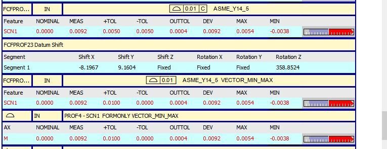
  • Your print shows profile only, which says it doesn't matter where this is as long as it holds its shape, If you think it to be necessary to show a plus value and a minus value in Xact, Then you need at least one Datum in my example Datum "C" is my Z surface so I am controlling my one direction but my "X" and "Y" of my scan has no particular place to be, so in the "x" and "Y" there is no set zero, until after the scan based off the hits with best fit creates it's own zero, hence the total value instead of the split value, in my example you'll see datum shift below, because my Datum "C" levels and constrains "Z". "Z" is allowed to Rotate but "X" and "Y" can not because of leveling Z and Z can not shift because "C" origins "Z" not allowing it to move, but "X" and "Y" are allow to shift (no particular place to be) . All this being said if you want to split the tolerance according to your print, and you want to use Xact, Then choose either Datum "D" or Datum "C" in your profile callout, and report your MAX and MIN, these are really your most important numbers anyways. If you use legacy the only choices you have is no constraint or all constraint. below is no constraint


  • I have been looking into Zeiss for a while, we conform to ASME Y14.5M. I remember being told that Calypso uses ISO, but it can report similar results as ASME. As a matter of fact ASME 2018 is moving in that direction. ASME does not yet use the myriad of modifiers available to ISO. ASME Y14.5M 2009 reports profile differently than than ISO and ASME Y14.5M 2018. So yes you could conform to one and not the other in some cases. A really big deal with high precision parts that have curved / spherical geometry.

    No Datums, no orientation or location considered. Just form and you have a choice with the fitting. LSQ or Default. See help file one is more important / useful to the machinist
  • Thanks KIRBSTER for the response. This is the report the Boss wanted to see.

    What is the best way to measure this type of profile call out?
    I wrote program to take vector points or should I measure as circles and lines?
  • Thanks KIRBSTER for the response. This is the report the Boss wanted to see.

    What is the best way to measure this type of profile call out?
    I wrote program to take vector points or should I measure as circles and lines?


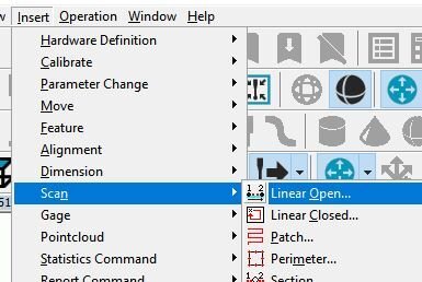
    Well I have a scanner, but I would suggest points if you don't have a scanner. You can still use Linear Open Scan, if you know how to use them with a Touch probe. Insert/Scan/Linear Open. If you don't have this, then points and make a constructed Feature Set out of those points.