hexagon logo

Iterative Alignment Error

Hello all.

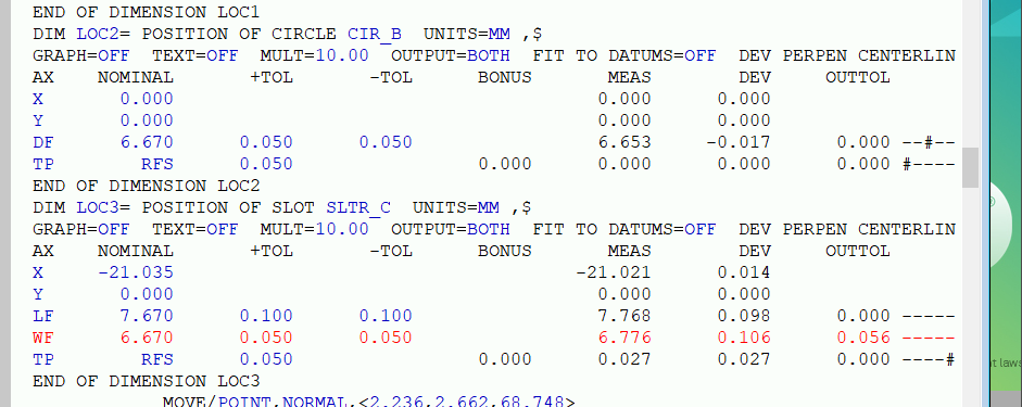
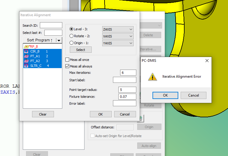
I made a very simple Iterative alignment program. I ran couple times, sometime it was good, but most pop out error message: Iterative Alignment Error. It is a very simple structure:
On plane A , there is a circle B and round slot C, I picked up 2 points beside B and C. Why it failed?

Thank you ( I uploaded the program and some images from the screen)


Attached Files
Parents
  • Also, don't use the slot directly, create a cast point from it and use that instead. The help file clearly states that slots are not recommended: Iterative Alignment Rules (hexagonmi.com)
  • Thank you Neil.

    Just one more silly question....

    Say you're working with a CAD file and a physical fixture that has all of the A-Nets / 4-WAY / 2-WAY positional locator pins that are MMC and built square to grid.

    First I do an iterative alignment off of the 3 tooling bushings built into the fixture with stamped nominals and make sure your vectors are 0,0,1 with 3 sample hits for each circle you are creating.... This aligns the fixture...

    Next I go into DCC mode and manually take a hit on the A-Nets and find the nearest CAD button with Snap on for the vector points in the open feature window, however when I get to the 4-Way and 2-Way locating pins I'll just select those in CAD (I make the Slot into a Circle) and I don't take a surface hit as they usually don't have a plane or net accompanying them.

    I then perform another Iterative Alignment off of the measured Datums and then go over the same features to make sure everything has fallen into spec within +/- 0.05mm

    Is this a correct way of aligning the fixture and later measuring parts off of the fixture for part layouts?

    Please correct me on anything if I am wrong.

    Thank you.
Reply
  • Thank you Neil.

    Just one more silly question....

    Say you're working with a CAD file and a physical fixture that has all of the A-Nets / 4-WAY / 2-WAY positional locator pins that are MMC and built square to grid.

    First I do an iterative alignment off of the 3 tooling bushings built into the fixture with stamped nominals and make sure your vectors are 0,0,1 with 3 sample hits for each circle you are creating.... This aligns the fixture...

    Next I go into DCC mode and manually take a hit on the A-Nets and find the nearest CAD button with Snap on for the vector points in the open feature window, however when I get to the 4-Way and 2-Way locating pins I'll just select those in CAD (I make the Slot into a Circle) and I don't take a surface hit as they usually don't have a plane or net accompanying them.

    I then perform another Iterative Alignment off of the measured Datums and then go over the same features to make sure everything has fallen into spec within +/- 0.05mm

    Is this a correct way of aligning the fixture and later measuring parts off of the fixture for part layouts?

    Please correct me on anything if I am wrong.

    Thank you.
Children
No Data