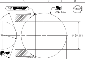
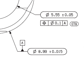
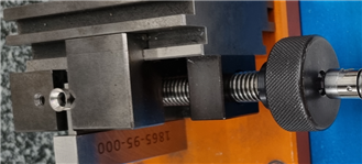
Your Products have been synced, click here to refresh
There's a lot going on here.
I would look into a few fundamental thoughts before red-tagging it, especially if it's a sample set of a larger lot or batch.
1: Can you affirm the OOS condition using another means? I know 0.0008" / 0.020mm is too tight to determine with a caliper, but i'm sure if you throw it on a surface plate with a v-block and indicate the ID while spinning the part, you'd be able to affirm concentricity to the OD with ease.
Note: if both cylinders are tri-lobed this could potentially be invisible in a v-block, so look at your form error plots of the circles for patterns/lobing.
2: How is it manufactured?
3: What kind of screwup during manufacture, could have caused this condition?
4: How could it have been manufactured and brought to you as presumably acceptable?
Another possible contributor is your probe itself. Since it's such a small diameter, I'm guessing you are using a smaller probe? 1mm? the Probe diameter-to-shank clearance for a 1mm probe is miniscule (the 1mm probe with TC shank gives you just 0.010" between the shank and the edge of the sphere, when it's made perfectly) and something like a glob of glue at the sphere, or a slightly bent tip, no matter the calibration results of that probe can interact when you start probing at a depth into the part.
If you don't assign a rotational datum, the demon simply refers to the rotation as being square to the machine's volume, about your local level plane. The floating tetrahedron animation in the graphic view is a tool to make sure you clearly isolate all 6DOF to the part's constraints. If there's no rotational datum on the print, technically, you don't need to establish one in the alignment, unless you are trying to lock down a possible issue with the part or method.
I agree with you, no need to lock rotation in a circular part that has no rotational element. I need to measure only 2 dias (outer, inner) and the position of one to another.
(considering that the leveling is not the same vector as the rotation).
I just purposed to lock the rotation trying to explain the defects. If you re-measure all the features after rotation, does it change anything ? (particulary if you level on the top plane after rotation - just to check, I understand you cannot do it on a lot of parts !!!!!)
I think you should post the code (even if it's in french ), or a picture of the fixturing
LOADPROBE/PROBE1 TIP/T1A0B0, SHANKIJK=0, 0, 1, ANGLE=0 RECALL/ALIGNMENT,EXTERNAL,APS-PDEA-103722425_A MODE/DCC PREHIT/1.5 RETRACT/1.5 CLEARP/ZPLUS,200,ZPLUS,0,OFF MOVE/CLEARPLANE MOVE/POINT,NORMAL,<0,0,200> CER1 =FEAT/CONTACT/CIRCLE/DEFAULT,CARTESIAN,IN,LEAST_SQR THEO/<0,0,-2>,<0,0,1>,5.55 ACTL/<-0.6152,-0.271,-2>,<0,0,1>,5.5548 TARG/<0,0,-2>,<0,0,1> START ANG=0,END ANG=360 ANGLE VEC=<0,-1,0> DIRECTION=CW SHOW FEATURE PARAMETERS=NO SHOW CONTACT PARAMETERS=NO CLEARP/ZPLUS,5,ZPLUS,0,ON A1 =ALIGNMENT/START,RECALL:APS-PDEA-103722425_A,LIST=YES ALIGNMENT/TRANS,XAXIS,CER1 ALIGNMENT/TRANS,YAXIS,CER1 ALIGNMENT/END MOVE/CLEARPLANE CER2 =FEAT/CONTACT/CIRCLE/DEFAULT,CARTESIAN,OUT,LEAST_SQR THEO/<0,0,-0.5>,<0,0,1>,8.99,0 ACTL/<-0.0008,0.0641,-0.5>,<0,0,1>,8.9976,0 TARG/<0,0,-0.5>,<0,0,1> START ANG=180,END ANG=540 ANGLE VEC=<0,-1,0> DIRECTION=CW SHOW FEATURE PARAMETERS=YES VOID DETECTION=NO REMEASURE=NO SURFACE=THICKNESS_NONE,0 MEASURE MODE=NOMINALS RMEAS=NONE,NONE,NONE CIRCULAR MOVES=CIRCULAR GRAPHICAL ANALYSIS=NO FEATURE LOCATOR=NO,NO,"" SHOW CONTACT PARAMETERS=YES NUMHITS=7,DEPTH=0,PITCH=0 SAMPLE METHOD=SAMPLE_HITS SAMPLE HITS=0,SPACER=0 AVOIDANCE MOVE=NO,DISTANCE=10 FIND HOLE=DISABLED,ONERROR=NO,READ POS=NO SHOW HITS=NO ASSIGN/V1=CER2.R-0.20 MOVE/CLEARPLANE PNT1 =FEAT/CONTACT/VECTOR POINT/DEFAULT,POLAR THEO/<V1,90,0>,<0,0,1> ACTL/<4.2989,89.9965,0.3247>,<0,0,1> TARG/<V1,90,0>,<0,0,1> SNAP=NO SHOW FEATURE PARAMETERS=YES SURFACE=THICKNESS_NONE,0 MEASURE MODE=NOMINALS RMEAS=NONE,NONE,NONE GRAPHICAL ANALYSIS=NO FEATURE LOCATOR=NO,NO,"" SHOW CONTACT PARAMETERS=YES AVOIDANCE MOVE=NO,DISTANCE=10 SHOW HITS=NO A4 =ALIGNMENT/START,RECALL:A1,LIST=YES ALIGNMENT/TRANS,ZAXIS,PNT1 ALIGNMENT/END PLN1 =FEAT/CONTACT/PLANE/DEFAULT,CARTESIAN,TRIANGLE,LEAST_SQR THEO/<0,0,0>,<0,0,1> ACTL/<-0.0004,-0.019,0.1625>,<-0.0037827,0.0390827,0.9992288> TARG/<0,0,0>,<0,0,1> ANGLE VEC=<0,-1,0>,RADIAL SHOW FEATURE PARAMETERS=NO SHOW CONTACT PARAMETERS=YES NUMHITS=7,NUMROWS=1 SPACER=V1 AVOIDANCE MOVE=NO,DISTANCE=2 SHOW HITS=NO DIM PLAT1= FLATNESS OF PLANE PLN1 UNITS=MM ,$ GRAPH=OFF TEXT=OFF MULT=100.00 ARROWDENSITY=100 OUTPUT=BOTH AX NOMINAL +TOL -TOL MEAS DEV OUTTOL M 0.0000 0.0150 0.0000 0.0195 0.0195 0.0045 > A2 =ALIGNMENT/START,RECALL:A1,LIST=YES ALIGNMENT/LEVEL,ZPLUS,PLN1 ALIGNMENT/TRANS,XAXIS,CER2 ALIGNMENT/TRANS,YAXIS,CER2 ALIGNMENT/TRANS,ZAXIS,PLN1 ALIGNMENT/END MOVE/CLEARPLANE CER8_99 =FEAT/CONTACT/CIRCLE/DEFAULT,CARTESIAN,OUT,LEAST_SQR THEO/<0,0,-0.5>,<0,0,1>,8.99,0 ACTL/<-0.0003,-0.0014,-0.5>,<0,0,1>,8.9912,0 TARG/<0,0,-0.5>,<0,0,1> START ANG=-90,END ANG=270 ANGLE VEC=<0,-1,0> DIRECTION=CW SHOW FEATURE PARAMETERS=NO SHOW CONTACT PARAMETERS=YES NUMHITS=23,DEPTH=0,PITCH=0 SAMPLE METHOD=SAMPLE_HITS SAMPLE HITS=0,SPACER=0 AVOIDANCE MOVE=NO,DISTANCE=10 FIND HOLE=DISABLED,ONERROR=NO,READ POS=NO SHOW HITS=NO A3 =ALIGNMENT/START,RECALL:A2,LIST=YES ALIGNMENT/TRANS,XAXIS,CER8_99 ALIGNMENT/TRANS,YAXIS,CER8_99 ALIGNMENT/END MOVE/CLEARPLANE CER5_55MI =FEAT/CONTACT/CIRCLE/DEFAULT,CARTESIAN,IN,MAX_INSC THEO/<0,0,-3>,<0,0,1>,5.55 ACTL/<-0.0056,0.0004,-3>,<0,0,1>,5.544 TARG/<0,0,-3>,<0,0,1> START ANG=0,END ANG=360 ANGLE VEC=<0,-1,0> DIRECTION=CW SHOW FEATURE PARAMETERS=NO SHOW CONTACT PARAMETERS=YES NUMHITS=17,DEPTH=0,PITCH=0 SAMPLE METHOD=SAMPLE_HITS SAMPLE HITS=0,SPACER=0 AVOIDANCE MOVE=NO,DISTANCE=10 FIND HOLE=DISABLED,ONERROR=NO,READ POS=NO SHOW HITS=NO SCN1 =FEAT/SET,CARTESIAN THEO/<0,0,-3>,<0,0,1> ACTL/<-0.0024,0.0008,-2.9992>,<0,0,1> CONSTR/SET,BASIC,CER5_55MI.HIT[1..CER5_55MI.NUMHITS],, CER5_55LS =FEAT/CIRCLE,CARTESIAN,IN,LEAST_SQR,NO THEO/<0,0,-3>,<0,0,1>,5.55 ACTL/<-0.005,0.0017,-2.9992>,<0,0,1>,5.5525 CONSTR/CIRCLE,BF,2D,SCN1,, OUTLIER_REMOVAL/OFF,3 FILTER/OFF,UPR=0 MOVE/CLEARPLANE
DIM LOC1= LOCATION OF CIRCLE CER8_99 UNITS=MM ,$ GRAPH=OFF TEXT=OFF MULT=10.00 OUTPUT=BOTH HALF ANGLE=NO AX NOMINAL +TOL -TOL MEAS DEV OUTTOL D 8.9900 0.0150 -0.0150 8.9912 0.0012 0.0000 # RN 0.0000 0.0300 0.0000 0.0044 0.0044 0.0000 # END OF DIMENSION LOC1 DIM LOC2= LOCATION OF CIRCLE CER5_55MI UNITS=MM ,$ GRAPH=OFF TEXT=OFF MULT=10.00 OUTPUT=BOTH HALF ANGLE=NO AX NOMINAL +TOL -TOL MEAS DEV OUTTOL D 5.5500 0.0500 -0.0500 5.5440 -0.0060 0.0000 # RN 0.0000 0.1000 0.0000 0.0111 0.0111 0.0000 # END OF DIMENSION LOC2 DIM LOC3= POSITION OF CIRCLE CER5_55LS UNITS=MM ,$ GRAPH=OFF TEXT=OFF MULT=10.00 OUTPUT=BOTH FIT TO DATUMS=OFF DEV PERPEN CENTERLINE=OFF DISPLAY=DIAMETER AX NOMINAL +TOL -TOL BONUS MEAS DEV OUTTOL X 0.0000 -0.0050 -0.0050 Y 0.0000 0.0017 0.0017 TP RFS 0.1000 0.0000 0.0106 0.0106 0.0000 # END OF DIMENSION LOC3
Are you clamping the part? Or how do you secure it in the V-block? Glue?
Just a question : why do you use start angle once at 0, once at 180 and once at -90, always with angle at Yminus ?
© 2024 Hexagon AB and/or its subsidiaries. | Privacy Policy | Cloud Services Agreement |