hexagon logo

Loopity Loops (and how to offset em')

Greetings fellow metrologists

I would like some help on my loop problem.
I have to create a loop to measure many parts simultaneously. I have done this before, but it was cylindrical parts, so it was quite easy to create the offsets in the loops.
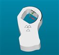
But now i have this not-so-round part and its coordinatesystem doesnt match cmm axis
so im not quite sure how to go about this problem.
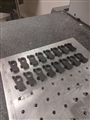
(see picture for part coordinates and how i will place them on the cmm). they will be placed in mulitple rows.

ty guys, u always help me

Attached Files
Parents
  • Maybe:

    Measure the thread distances, align on them (cir-cir) and the base plate plane, set zero in one of them.
    Move to DCC, measure your part, align accordingly (so it matches the part CAD).
    Evaluate.
    Recall the first alignment.
    Offset the alignment to the next set of thread distances.
    Jump up to the DCC section of the actual part measurement.
    Evaluate.
    Recall the first alignment.
    Offset... bla, bla

    Rinse, repeat.
  • If you choose to go by the thread bosses, you are right but that is only valid for all features PRIOR to your part alignment (the features measured in the thread boss alignment will not be used for evaluation anyway). As soon as you have managed the part alignment, you will go by the CAD. So the only thing the thread boss alignment should do is to "find" and measure the part features you will use for the part alignment.
Reply
  • If you choose to go by the thread bosses, you are right but that is only valid for all features PRIOR to your part alignment (the features measured in the thread boss alignment will not be used for evaluation anyway). As soon as you have managed the part alignment, you will go by the CAD. So the only thing the thread boss alignment should do is to "find" and measure the part features you will use for the part alignment.
Children
No Data