hexagon logo

Loopity Loops (and how to offset em')

Greetings fellow metrologists

I would like some help on my loop problem.
I have to create a loop to measure many parts simultaneously. I have done this before, but it was cylindrical parts, so it was quite easy to create the offsets in the loops.
But now i have this not-so-round part and its coordinatesystem doesnt match cmm axis
so im not quite sure how to go about this problem.
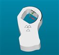
(see picture for part coordinates and how i will place them on the cmm). they will be placed in mulitple rows.

ty guys, u always help me

Attached Files
Parents
  • Maybe:

    Measure the thread distances, align on them (cir-cir) and the base plate plane, set zero in one of them.
    Move to DCC, measure your part, align accordingly (so it matches the part CAD).
    Evaluate.
    Recall the first alignment.
    Offset the alignment to the next set of thread distances.
    Jump up to the DCC section of the actual part measurement.
    Evaluate.
    Recall the first alignment.
    Offset... bla, bla

    Rinse, repeat.
Reply
  • Maybe:

    Measure the thread distances, align on them (cir-cir) and the base plate plane, set zero in one of them.
    Move to DCC, measure your part, align accordingly (so it matches the part CAD).
    Evaluate.
    Recall the first alignment.
    Offset the alignment to the next set of thread distances.
    Jump up to the DCC section of the actual part measurement.
    Evaluate.
    Recall the first alignment.
    Offset... bla, bla

    Rinse, repeat.
Children
  • Ty VPT, you always have an answer
    I will try this,
    how can i go from measuring the threads (dubbarna in the picture) straight to DCC on the part?
    i dont have cad of how the part is placed on the plate against the dubbs.
  • Align it and measure the part features for the part alignment "manually" in DCC, either by manual/learned features or by "learning" autofeatures (open autofeature dialog and manually take points to fill the XYZ, IJK in the dialog).

    Or, measure the part features for the part alignment manually (don't bother about the thread bosses), go to DCC and create the measurements/evaluations for the part. Offset the alignment with the distance between the thread bosses in X, still in DCC and it should measure the next part.
  • Ah oki!
    Thing is i dont know the what the nominal ijks are relative to the the alignment of the threads.
    So only option i see then is to manually probe the features, so i use the measured ijk as nominal ijk (besides top plane, thats easy to figure out)
  • If you choose to go by the thread bosses, you are right but that is only valid for all features PRIOR to your part alignment (the features measured in the thread boss alignment will not be used for evaluation anyway). As soon as you have managed the part alignment, you will go by the CAD. So the only thing the thread boss alignment should do is to "find" and measure the part features you will use for the part alignment.