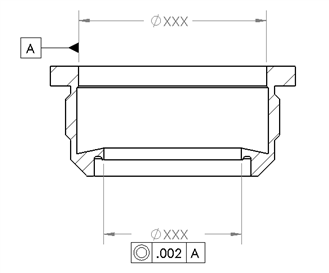
I have two cylinders on a part that need to be concentric within .002". I noticed that on some parts, not all, the concentricity reports out of tolerance at .0039 for example but then when I rotate the part 180 degrees, the concentricity is suddenly .002 or less.
I align the part by measuring a top plane, leveling to this and setting z origin. Then I measure a circle with 9 hits and make this the x and y origin. Im not locking rotation as I really dont think it matters in this case since its a circular part anyway. I then measure the datum as a 3 level cylinder with 9 hits each level, then measure the next cylinder 9 hits 3 levels.
I don't see how rotating it 180 degrees changes anything especially since I'm taking 9 hits at each level on diameters less than 2.5 inches I should be, in my mind, hitting enough spots to capture anything weird going on with the part. What am I doing wrong here? Thanks.
What probe do you use ? (type of probe, tip and stem diameters)
What is the value of cylindricity ?
Do you take the 9 hits in the same way, or do you turn them also of 180° ?
Is it possible that the probe shanks ?
Yep. We need more info. I would add: What's the touch speeds? Calibration & inspection must have the touch speeds. Where the points taken? Are the points on the measured cylinder in the identical locations (in x & y) as the points taken on the datum? Is the part tilted or moving? Try to use points alone & construct either circles or cylinders. I would probably use circles instead derived from autovector points. Also checking concentricity with points is not really a good idea. Scanning with hundreds of points will be better if you have scanning probe head. Otherwise consider using position control instead.
Need a visual here as rotating 180 has multiple means.....spinning the part ( around Z axis ) or fliping it over ( Z+ is now Z- ) ? This have something do to with leveling on the plane ? Wouldnt you level to the CYLINDER / DATUM ?
In this case 180 means spinning the part around the Z axis. I can try leveling to the cylinder although I cant think of a reason that changes things very much. As long as the cmm knows where the part is in space and then takes hits accordingly why would it matter which plane is used to level it?
All the difference in the world if you ask me. Think c-bore into material but its at a slight angle to the face you leveld on. Looking down in Z at the features you tool in the hole. They dont look so concentric anymore do they ? Without code / print all we can do here is make assumptions.
I used a 2x20mm touch trigger probe and a 3x50mm. Cylindricity on the datum .00054" & conc. .0027" and rotated 180 its .00045" & conc. .0014. cylindricity on the other feature .00027 and rotated 180 its .00018 I dont think its shanking out because i think the diameters would be out of spec if it was. I take the 9 hits the same way each time only the part is rotated around the z axis.