hexagon logo

Construct Plane: using 2 surfaces what is the best approach?

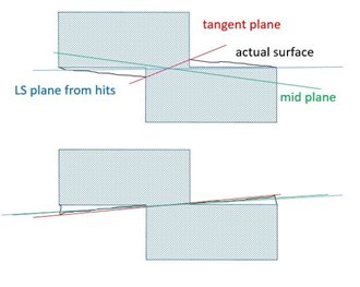
I have a datum that is 2 separate plane surfaces with opposing vectors but on the same center line.

What is the best approach: creating a few independent points on both surfaces and combining them into one plane OR creating 2 separate planes and then Constructing a plane from them?

  • yes you are correct
    in line with each other and on center to origin
  • I'm not sure why people are advocating a width in this example. I'm not saying it's wrong but from the description it doesn't sound like in terms of function it behaves as a width.

    I'm not even sure if it would be a valid datum.

    I'm picturing two nominally coplaner planes but facing opposite directions from each other, the fact they're nominally coplaner but facing opposite directions suggests to me they're offset from each other?


    Oh, you're right.

    Sorry BIGWIG7. I misunderstood the question. Re-reading it now, I see that you explained that they are coplanar (on the same CL).

    I'm inclined to try NinjaBadger's idea.

    With a Width or a Midplane I would worry that the vector would not calculate consistently. It seems like it may decide to flip the measured vector on you between runs depending on which surface is higher in the current alignment.

  • Widths are usually fine but depending on the algorithm used, you can run into a lot of issues. I've ran into a lot more fitting errors when using min_circ widths than using Least Squares.
  • Not sure that an accurate (and standard) solution exists...
    I would call the designer...
  • That's interesting. I haven't had an issue with using widths yet, even when used to clock, but I'll keep that in mind. I started using widths because I run into a lot of MMB cases and I like that I can dimension it directly as well.
  • Construct a plane out of the two planes. Not sure if this would work being two separate vectors.

    One thought:

    PLN1 =FEAT/CONTACT/PLANE/DEFAULT,CARTESIAN,TRIANGLE,LEAST_SQR
    THEO/<25,0,0>,<0,0,1>
    ACTL/<25,0,0>,<0,0,1>
    TARG/<25,0,0>,<0,0,1>
    ANGLE VEC=<1,0,0>,RADIAL
    SHOW FEATURE PARAMETERS=NO
    SHOW CONTACT PARAMETERS=YES
    NUMHITS=5,NUMROWS=1
    SPACER=6
    AVOIDANCE MOVE=NO
    SHOW HITS=NO
    PLN2 =FEAT/CONTACT/PLANE/DEFAULT,CARTESIAN,TRIANGLE,LEAST_SQR
    THEO/<-25,0,0>,<0,0,-1>
    ACTL/<-25,0,0>,<0,0,-1>
    TARG/<-25,0,0>,<0,0,-1>
    ANGLE VEC=<1,0,0>,RADIAL
    SHOW FEATURE PARAMETERS=NO
    SHOW CONTACT PARAMETERS=YES
    NUMHITS=5,NUMROWS=1
    SPACER=6
    AVOIDANCE MOVE=NO
    SHOW HITS=NO
    PLN3 =FEAT/PLANE,CARTESIAN,TRIANGLE,NO
    THEO/<-25,0,0>,<0,0,1>
    ACTL/<-25,0,0>,<0,0,1>
    CONSTR/PLANE,REV,PLN2
    PLN4 =FEAT/PLANE,CARTESIAN,TRIANGLE,NO,LEAST_SQR
    THEO/<0,0,0>,<0,0,1>
    ACTL/<0,0,0>,<0,0,1>
    CONSTR/PLANE,BF,PLN1.HIT[1..PLN1.NUMHITS,PLN3.HIT[1..PLN3.NUMHITS],,
    OUTLIER_REMOVAL/OFF,3
    FILTER/OFF,WAVELENGTH=0​


    Then you could play around with primary datum fitting algorithms.
  • i love all the input. just shows the community how many people have differing ideas on how to evaluate parts.
  • The people who draw the part. He should know what the datum is made for, so he could help to choose the best solution to measure.
  • I think individual points will give you the best flexibility. You can make 2 BF-RECOMP planes, filter as desired, reverse 1, if desired. _____Alternately, you could make individual mini-alignments of each plane, then re-probe normal to the improved vector of each half. I think that would allow you to build one best-fit plane. Never tried it, but theoretically that would work.