hexagon logo

True position Question

Hello guys,

Sorry for the dump question (and draft paint image) but I am a bit confused:


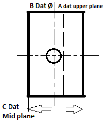
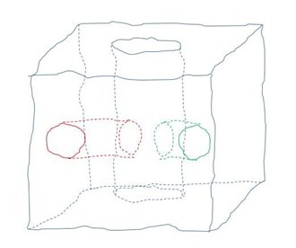
I have a TP callout for the hole (center of image) on a part like that. Datum A is the Upper plane (basic dimension value not important), Datum B is the vertical Ø through the part as displayed in dashed lines and Datums C as per picture. The callout is A/B/C and I was wondering since C is controlling the rotation in this datum structure, it would be wrong to control this hole as a circle right ? It would need to be a cylinder...
Thanks in advance for your help Slight smile
  • In theory, all holes are cylinders, not circles.... In practice, the choice of measuring as a circle or a cylinder is often dependent on how thick the material is and the process used to produce the hole.
  • That's why I am asking actually to assess the possibility of taking a circle since the available depth is of 1 mm or something :P
  • Assuming that there's not a tight Position tolerance and the feature has good form, I'd be inclined to measure the feature as a circle.
  • By upper plane, you mean -A- is the surface that the hole you are inspecting is drilled in to? If so, A | B controls everything except translation up/down as drawn.

    If you mean -A- is the surface -B- is drilled in, then -C- is restraining rotation around A and B, since B won't help there and all degrees of freedom are constrained.

    As far as what I'd choose, I generally look at how it was made. In a vise side milling the two planes making -C- and drilling the hole you are inspecting? Hole is relatively shallow? Circle.
    As described above, but hole is LONG (compared to the diameter, 5 times the Ø or worse I consider long), cylinder.
    -C- made on a different operation than the hole in question and it is deeper than 1/4 inch? cylinder. Shorter than 1/4 inch, circle.
    -C- made on two different operations so the planes might not even be parallel? Cylinder no matter how deep.
    Hole is crossing -B- so it has interupted cuts and it is a high speed steel drill? Cylinder.
    Hole is crossing another hole (not as you pictured, but off-center so the drill is hitting on like 100° to 300° of it's diameter? Cylinder.
    Hole is threaded? Circle.
    Hole is threaded and engineer thought it was cute to put a projected tolerance zone? Cylinder with a LOT of profanity.
    Made by helically boring with an end mill and then reaming with two reamers (or three) stepping into the size? Circle.
    I don't know how it was made? Cylinder.

    Then, as Sid said, open tolerance compared to the depth of the hole? Circle, so long as that interupted cut thing didn't rear its head or it is really deep.
    Tight tolerance, cylinder.


    Thanks for the answer, in fact I was more interested about the theoretical part and how to deal with such a scenario. The geometry is way... way more complicated but I did a fast draft trying to explain the datum setup (apparently not sufficiently). The dimensions and how small or big a hole shows is not important, it is just for reference. Upper plane is the Z+ axis if you have the part on the cmm and facing it from Y-

    The construction of the part and the methods are irrelevant also (part in development phase still).

    The way I see it Datum B is not really necessary as with a A/C callout you have everything constrained. Apparently the B datum is of more importance and thus constraining the translation in X axis leaving the rotation to datum C. Things get a bit complicated indeed when a TP callout for a hole has not the drilled plane as primary datum Slight smile
  • You can't use C for the rotation if B is listed second with A being Z+.

    B is capable of constraining K (rotation about Z) and therefore, being listed second, must do so.

    There is a method an engineer can use to state that the tertiary datum rather than secondary is constraining something, but you don't show that in your notation for the position.

    So, A constrains I and J rotations and Z translation.
    B constrains K rotation and X translation.
    C constrains nothing.
    Y translation is not constrained by anything.

    This is how it is written, and how it must be done. In your sketch, there is nothing for Y no matter what you use to halt the third rotation.

    If B and C were perpindicular to each other, rather than parallel, then you'd be fully constrained.

    Without special instructions, no datums yields to a subsequent datum.

    YOU can't SAY A just does the rotations because B is more important and holds Z. The standards are not written that way.
    The ENGINEER must WRITE if that is the case.

    Apparently, the brain trust making Y14.5 couldn't use I, J and K like EVERYONE in the industry (I wonder if this is U.S. only and that's why I think this?), I looked this up to get it right, they use U spinning around X, V spinning around Y and W spinning around Z.

    So, your FCF (I made up a tolerance since you didn't give one) of POS | Ø .014 RFS | A | B | C |
    Diametral tolerance zone of .014 regardless of feature size with
    A constraining U, V and Z
    B constraining W and X
    nothing for Y

    What you are suggesting in your words, B is more important for translation but C controls the spin would be written: POS | Ø .014 RFS | A [u, v, z] | B [x] | C [w] |
    Diametral tolerance zone of .014 regardless of feature size with
    A constraining U, V and Z
    B constraining X
    C constraining W
    nothing for Y


    This is Y14.5-2009, sec 4.23, pg 83, with a figure 4-46 on pg 84. You (the inspector) don't get to skip B in favor of C, the engineer has to write it. Of course, that doesn't stop the engineer from wanting it and not writing it because the engineer doesn't fully understand GD&T... but I'm being crazy, engineers ALWAYS understand GD&T perfectly, that's why they make threaded holes datums and apply MMB to them, I'm being silly. (HEAVY sarcasm if you couldn't read my tone in to that lol)
  • Without C, both red and green holes would be ok...

    Measuring as a circle should be enough (IMO)
  • Well you got also confused :P

    B cannot control the K rotation as its vector is K. A constrains 3 DOF as you wrote, B does 2 (but translation in Y is not needed in this case) and C is left to constrain Rotation. For me nothing wrong with the callout just that it get a bit complicated and can confuse a bit (you and me both apparently :P )
  • Without C, both red and green holes would be ok...
    {"data-align":"none","data-size":"medium","data-attachmentid":528283}
    Measuring as a circle should be enough (IMO)


    But if I measure as a circle (thus projected in I vector defined by datum A and C) what is the point of using the C datum in the callout all together? Wouldn't it be the same to write A/B only? (I am not questioning your suggestion btw, just wanna learn how this works Slight smile ; Learning from this example/post is more important that the actual problem I am facing).


  • But if I measure as a circle (thus projected in I vector defined by datum A and C) what is the point of using the C datum in the callout all together? Wouldn't it be the same to write A/B only? (I am not questioning your suggestion btw, just wanna learn how this works Slight smile ; Learning from this example/post is more important that the actual problem I am facing).


    Without datum C, the DRF is free to rotate about datum B. It can rotate until it is lined up with the hole where it will report 0 deviation from B, and only the deviation from datum A will be applied to the true position. You need to have datum C to lock the rotation about datum B down so that the deviation from datum B (normal to the midplane of datum C) is also taken into account.

    If you measure the hole as a circle without datum C, you will have 0 deviation from datum B. If you measure the hole as a cylinder, it will only report the deviation of the cylinder from datum B perpendicular to the hole cylinder. If there is any angular deviation between the cylinder and datum C, then this will still be an incorrect calculation for the true position. In every case, the deviation from datum A will be calculated correctly