hexagon logo

True position Question

Hello guys,

Sorry for the dump question (and draft paint image) but I am a bit confused:
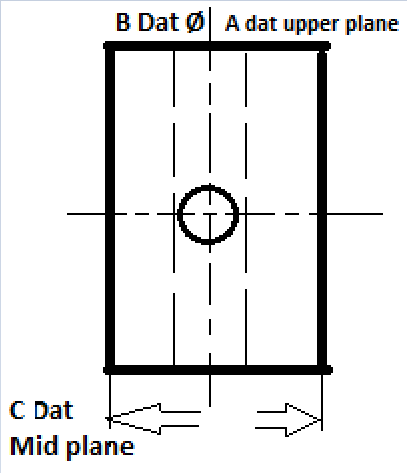


I have a TP callout for the hole (center of image) on a part like that. Datum A is the Upper plane (basic dimension value not important), Datum B is the vertical Ø through the part as displayed in dashed lines and Datums C as per picture. The callout is A/B/C and I was wondering since C is controlling the rotation in this datum structure, it would be wrong to control this hole as a circle right ? It would need to be a cylinder...
Thanks in advance for your help Slight smile
Parents
  • By upper plane, you mean -A- is the surface that the hole you are inspecting is drilled in to? If so, A | B controls everything except translation up/down as drawn.

    If you mean -A- is the surface -B- is drilled in, then -C- is restraining rotation around A and B, since B won't help there and all degrees of freedom are constrained.

    As far as what I'd choose, I generally look at how it was made. In a vise side milling the two planes making -C- and drilling the hole you are inspecting? Hole is relatively shallow? Circle.
    As described above, but hole is LONG (compared to the diameter, 5 times the Ø or worse I consider long), cylinder.
    -C- made on a different operation than the hole in question and it is deeper than 1/4 inch? cylinder. Shorter than 1/4 inch, circle.
    -C- made on two different operations so the planes might not even be parallel? Cylinder no matter how deep.
    Hole is crossing -B- so it has interupted cuts and it is a high speed steel drill? Cylinder.
    Hole is crossing another hole (not as you pictured, but off-center so the drill is hitting on like 100° to 300° of it's diameter? Cylinder.
    Hole is threaded? Circle.
    Hole is threaded and engineer thought it was cute to put a projected tolerance zone? Cylinder with a LOT of profanity.
    Made by helically boring with an end mill and then reaming with two reamers (or three) stepping into the size? Circle.
    I don't know how it was made? Cylinder.

    Then, as Sid said, open tolerance compared to the depth of the hole? Circle, so long as that interupted cut thing didn't rear its head or it is really deep.
    Tight tolerance, cylinder.


    Thanks for the answer, in fact I was more interested about the theoretical part and how to deal with such a scenario. The geometry is way... way more complicated but I did a fast draft trying to explain the datum setup (apparently not sufficiently). The dimensions and how small or big a hole shows is not important, it is just for reference. Upper plane is the Z+ axis if you have the part on the cmm and facing it from Y-

    The construction of the part and the methods are irrelevant also (part in development phase still).

    The way I see it Datum B is not really necessary as with a A/C callout you have everything constrained. Apparently the B datum is of more importance and thus constraining the translation in X axis leaving the rotation to datum C. Things get a bit complicated indeed when a TP callout for a hole has not the drilled plane as primary datum Slight smile
Reply
  • By upper plane, you mean -A- is the surface that the hole you are inspecting is drilled in to? If so, A | B controls everything except translation up/down as drawn.

    If you mean -A- is the surface -B- is drilled in, then -C- is restraining rotation around A and B, since B won't help there and all degrees of freedom are constrained.

    As far as what I'd choose, I generally look at how it was made. In a vise side milling the two planes making -C- and drilling the hole you are inspecting? Hole is relatively shallow? Circle.
    As described above, but hole is LONG (compared to the diameter, 5 times the Ø or worse I consider long), cylinder.
    -C- made on a different operation than the hole in question and it is deeper than 1/4 inch? cylinder. Shorter than 1/4 inch, circle.
    -C- made on two different operations so the planes might not even be parallel? Cylinder no matter how deep.
    Hole is crossing -B- so it has interupted cuts and it is a high speed steel drill? Cylinder.
    Hole is crossing another hole (not as you pictured, but off-center so the drill is hitting on like 100° to 300° of it's diameter? Cylinder.
    Hole is threaded? Circle.
    Hole is threaded and engineer thought it was cute to put a projected tolerance zone? Cylinder with a LOT of profanity.
    Made by helically boring with an end mill and then reaming with two reamers (or three) stepping into the size? Circle.
    I don't know how it was made? Cylinder.

    Then, as Sid said, open tolerance compared to the depth of the hole? Circle, so long as that interupted cut thing didn't rear its head or it is really deep.
    Tight tolerance, cylinder.


    Thanks for the answer, in fact I was more interested about the theoretical part and how to deal with such a scenario. The geometry is way... way more complicated but I did a fast draft trying to explain the datum setup (apparently not sufficiently). The dimensions and how small or big a hole shows is not important, it is just for reference. Upper plane is the Z+ axis if you have the part on the cmm and facing it from Y-

    The construction of the part and the methods are irrelevant also (part in development phase still).

    The way I see it Datum B is not really necessary as with a A/C callout you have everything constrained. Apparently the B datum is of more importance and thus constraining the translation in X axis leaving the rotation to datum C. Things get a bit complicated indeed when a TP callout for a hole has not the drilled plane as primary datum Slight smile
Children
No Data