hexagon logo

RUNOUT - what's the correct way

Hello,

I'm faceing a problem with measuring RUNOUT on a 540mm tube.

Let me explain:

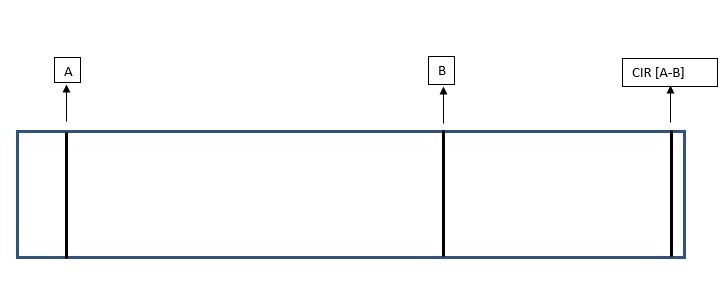
The tube consist of two datums - A and B. Datum A is at the front of the tube, Datum B is slightly off center on the opposite site. Datums defined out of circles, because measured cylinders are short in distance.

1. We need to measure what's the runout on a circle on the far side of the tube. RUNOUT DIA42 [A - B]. The problem is that with turning the tube on a fixture, we get up to 0.04 variation.
2. We need to measure whats the runout on a circle which is datum A looking at datum B - RUNOUT DIA_A . The problem is the same but with much bigger variation.

I know that form has a big impact on runout - form of datums are not the same.

What I've tried is and I don't know if this is correct:
I've constructed a cylinder out of two circles which are opposite and on the far side of the tube and did the alignment: level and origin on that cylinder- alignment is now in the middle of the tube.

When doing this, the RUNOUT on datum is better, we get the same variation - up to 0.04 and not up to 0.1. The datum [A-B] is measured the same as previous alignment.

Is there any other way?


Now I need to convince our technology, that we measure correct.


BR


  • To add more info:
    - 0° measured 0.01
    - 90° measured 0.051
    - 180° measured 0.069
    - 270° measured 0.058
    - 0°measurede 0.009
  • Could you produce a sketch of the drawing?

    You say 'Datum B is slightly off center on the opposite site'. Are you saying that the two diameters which produce datum system A-B aren't nominally concentric? Or are you saying Datum B is a little over halfway down the tube?

    Are these ID'd or OD's?
    What probing are you using & how long is it?
    How are you measuring the diameters, as complete circles or constructed from points? How many hits/points?
    What is the reported form of the circles in question?


  • Datums are nominally concentric.

    All of them are ID.
    I'm using touch trigger with Disc probe 200mm. I've tried with probe 8x225 ball tip - results are the same.
    Diameters are measured as complete circles - 4 points ATM
    The form of the circles: A approx 0.007, B approx 0.015 and they are not the same form.

    Let me add - the machining is two separate operations - 1st milling and then turning
  • Depending up your probing system 200mm may be far too long. If it's a TP20 or Tesa MP type probe then this is the case.

    You might get better results using more hits - these probes will give a tri-lobed (3 pointed) form, which gets bigger the longer the stylus. Using only 4 hits this will likely be skewed one way, assuming you're rotating the probe to get in each end this could have a significant impact.

    You also need to make sure the probe calibrations relate correctly to each other (i.e. they are calibrated at the same time on the same sphere location ideally).

    However, using this type probing for this (touch trigger probe with too long an extension) you are always going to be compromised in terms of accuracy and repeatability.


    If it's an X1-S-H, X3, X5 or an SP25 with the appropriate module then you should be okay, but you should still use more than 4 hits.

    For a 40mm diameter I'd probably use 13 to 17 hits.

    The same as above goes for probe calibration however.


    Probably more relevant is if neither A or B is big enough to measure as a cylinder (which would provide a stable datum to level to), then the drawing likely doesn't reflect how the part assembles and functions.

    That said you should be able to generate a stable A-B datum from two circles to evaluate the dimeter at the far end of the tube.

    You will never get good results check A to B if B isn't long enough (relative to the distance between A and B).

  • Our probing system is X1-S-H.

    Probe calibrations are always at the same time at the same sphere position.

    Repeatability of measurements - if we re-clamb on the same degrees - are max 0.001.

    So currently I'm leaning towards point density.

    I've increased number of points to 5 (probably going to increase it more) and repeatability with turning is much better ATM.

    Is there any "rule" on how many points per diameter size?

    The lenghts of Datums are 15mm and 16mm.


    Just for future reference:
    My way of doing alignments on tubes is like this:
    - front plane - perpendicular to cylinder - level + origin
    - front cylinder (aprox. 100mm in lenght) - origin on two axes

    Is this the correct way or should I do a fine alignment before dimensioning?
    You've mentioned - "Probably more relevant is if neither A or B is big enough to measure as a cylinder (which would provide a stable datum to level to), then the drawing likely doesn't reflect how the part assembles and functions." So if assuming the datum A or datum B would be long enough, I should level to one of them?

    Does alignment affect runout, concentricity or any other GD&T?

    Thanks for your help and explanation!
  • There's no real rules on number of points.

    Ideally you'd increase the number of hits until it's not making any difference, but experience comes into this a lot depending on size, tolerances and manufacturing method.

    There is a free NPL (UK's National Physics Laboratory) guide which talks about probing strategies - you should find it easily on google.

    Even at 15mm and 16mm you should measure as cylinders really.

    100mm long will actually give a more stable alignment than just going off the end face (so you level to the cylinder instead of the plane).

    Alignments can have an impact of the GD&T depending on which dimensioning method you're using (Legacy vs Xact/Geometric Tolerances) and even then depending on how you use them.
  • That's what I thought and I'm going with increasing number of points until there's no difference.

    Well I've tried with cylinders but the there's quite a deviation - almost impossible. Because on 15mm lenght we measure two circles like 4mm in between them.

    What leveling on cylinder does?

    Every GD&T dimensioning is done with Xact.
  • When checking runout the point density needs to be as high as practical to capture the form error, we use a minimum of 24 when using trigger probes and 1mm density with scanning heads.
  • Measure standing up, ideally with a rotary table
  • and whats your recommendation if he doesnt have a rotary table?