hexagon logo

Probing groove with Disc Styli hitting groove top

Hello all,

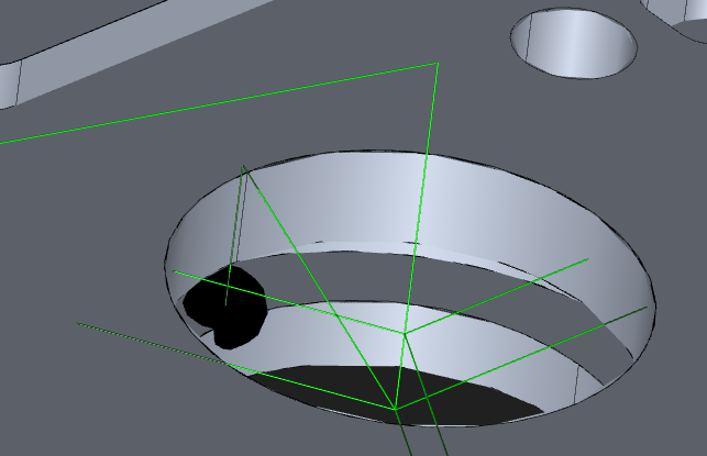
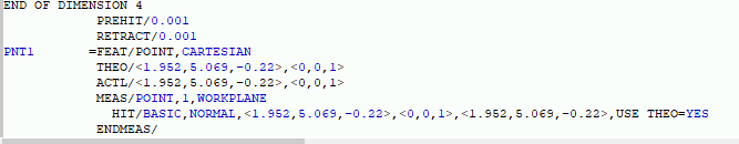
I've been digging into using a disc styli to measure a groove. I got everything programmed in 2019R2, and was checking the path lines. I noticed that when the probe moves to take a single hit on the depth of the groove, the prehit/retract will hit the top of the groove, by a lot. I adjusted the prehit/retract to .001", and I also removed the clearance plane and still no luck, it really didn't change anything.

I attached a couple pictures below for reference. I am probing the top circle first, then the groove diameter (no clearance plane) and then taking a single point for bottom of the groove (no clearance plane). I know the .001" prehit/retract is absurd, but I was just trying to see if I could get it to work at all.

I had no formal training in anything cmm programming, but have now been programming the CMM for 2 years (gotta love the "we'll hire a qualified person when the pandemic settles down more"). All my , learning has been from this forum, YouTube, or just trial and error, so i'm sure it's something simple i'm missing, I just can't quite figure this one out.

Any help would be appreciated.

Thanks


 ​​
Parents
  • Disc probes are not meant to take hits on the flat sides. The software is adding the probe radius (disc radius) when taking that hit. So, the distance you are seeing is the disc radius plus the .001 retract.

    If you want to experiment with taking hits like that, maybe you can turn off probe compensation?


    I do this as a reference to "get close" due to a distance callout. I have a 8mm disk that is 1.5mm thick. I take a point on top of the part and use the calibrated probe data to comp for my probe, then enter that into a generic and align to the generic point. Not necessarily a high precision point, but it gets me close enough to know where the part is in relation to another feature so I can bypass a bead.

    MOVE/CLEARPLANE
    PNT1 =FEAT/CONTACT/VECTOR POINT/DEFAULT,CARTESIAN
    THEO/<0,0,38.5>,<0,0,1>
    ACTL/<-0.001,0.01,35.427>,<0,0,1>
    TARG/<0,0,38.5>,<0,0,1>
    SNAP=NO
    SHOW FEATURE PARAMETERS=NO
    SHOW CONTACT PARAMETERS=NO
    ASSIGN/V4=PNT1.Z+((PROBEDATA("DIAMETER","T1A0B0")/2)-0.75)
    F1 =GENERIC/POINT,DEPENDENT,CARTESIAN,$
    NOM/XYZ,<0+0,0+0,38.5+0>,$
    MEAS/XYZ,<0+0,0+0,V4>,$
    NOM/IJK,<0+0,0+0,1+0>,$
    MEAS/IJK,<0+0,0+0,1+0>​
    
Reply
  • Disc probes are not meant to take hits on the flat sides. The software is adding the probe radius (disc radius) when taking that hit. So, the distance you are seeing is the disc radius plus the .001 retract.

    If you want to experiment with taking hits like that, maybe you can turn off probe compensation?


    I do this as a reference to "get close" due to a distance callout. I have a 8mm disk that is 1.5mm thick. I take a point on top of the part and use the calibrated probe data to comp for my probe, then enter that into a generic and align to the generic point. Not necessarily a high precision point, but it gets me close enough to know where the part is in relation to another feature so I can bypass a bead.

    MOVE/CLEARPLANE
    PNT1 =FEAT/CONTACT/VECTOR POINT/DEFAULT,CARTESIAN
    THEO/<0,0,38.5>,<0,0,1>
    ACTL/<-0.001,0.01,35.427>,<0,0,1>
    TARG/<0,0,38.5>,<0,0,1>
    SNAP=NO
    SHOW FEATURE PARAMETERS=NO
    SHOW CONTACT PARAMETERS=NO
    ASSIGN/V4=PNT1.Z+((PROBEDATA("DIAMETER","T1A0B0")/2)-0.75)
    F1 =GENERIC/POINT,DEPENDENT,CARTESIAN,$
    NOM/XYZ,<0+0,0+0,38.5+0>,$
    MEAS/XYZ,<0+0,0+0,V4>,$
    NOM/IJK,<0+0,0+0,1+0>,$
    MEAS/IJK,<0+0,0+0,1+0>​
    
Children
No Data