I would create a 2D line in the correct workplane, and dimension it. You could also project the line on a plane.
If you dimension a cylinder, create the line from different circles centers.
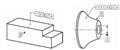
what exactly is that supposed to mean in this picture?
Is that a line of sight?
Isn't that in contradiction to the actual parallelism?
that looks kind of over-engineered (useless)?
Hi
Henniger123, it's the way to measure the parallelism.
Here, you measure the parallelism of the cylinder to the axis of A, in a plane parallel to B, so the defect in the other axis is not dimensionned (it's like a 2D parallelism, from a projection)
(the tolerance zone is oriented from another feature, established from an extracted feature of the workpiece, identifying the orientation of the tolerance zone.)
You can find the same symbol, with only one arrow (triangle) which is an intersection plane, with an arrow which is the direction feature indicator or a circle which is the collection plane indicator.
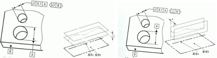
You evaluate it the same as normal the orientation plane symbol is just stating what direction to make the evaluation. In the example you have shown the bore parallel to 'A' could have 2 possible directions of parallelism converging/diverging or twist/rotate. By placing a direction plane parallel to Datum 'B' the bores are constrained to control converging/diverging, the perpendicular to datum 'B' controls the direction for twist/rotate.
I think the graphic for the perpendicular control is misleading and should show the control planes 90 deg to those drawn.
In the left case, the tolerance zone is parallele to B, in the right case, the tolerance zone is perp to B.
You could find both indications to change a Ø by a square zone.
In the attachment, there are only one triangle, so it indicates intersection planes.
Fortunately, I don't see those indications very often .
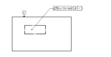
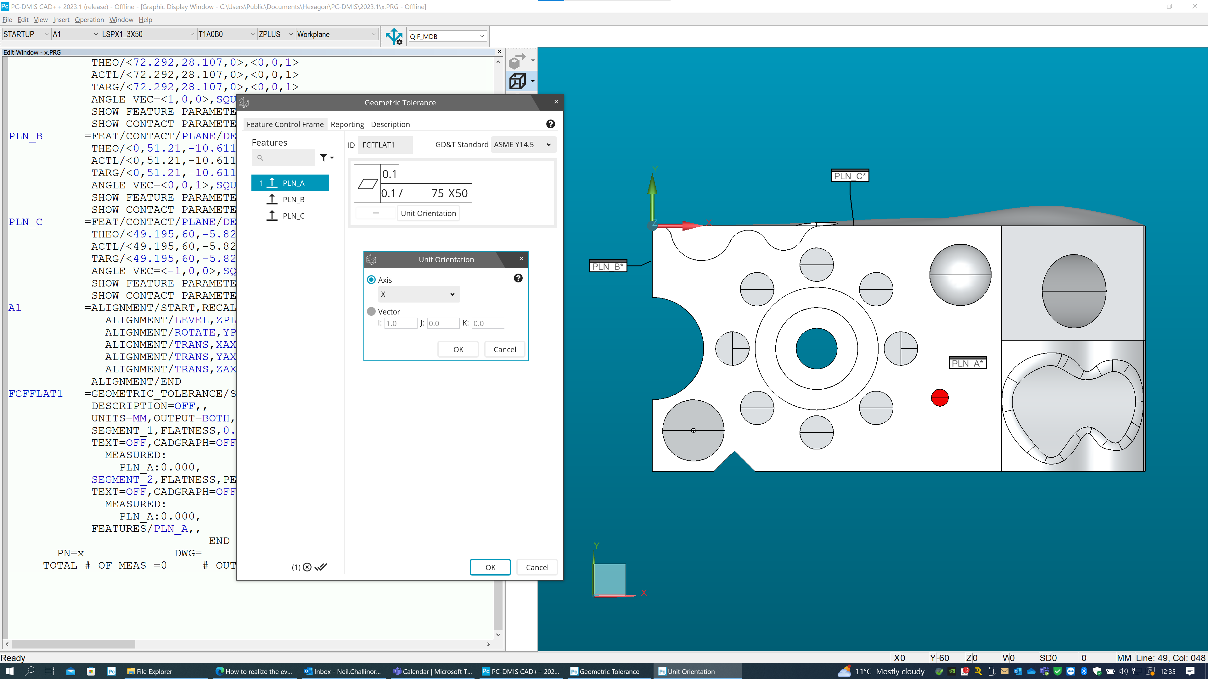
As other people have already explained, the orientation plane modifier controls the tolerance zone orientation. In this case you have a per-unit flatness over a 75x50 rectangular area. The orientation modifier is stipulating that this 75x50 rectangular area needs to be orientated with the longest side of the rectangle parallel to datum C. To achieve this in PC-DMIS, you need to create an alignment and then set the unit orientation accordingly - see my example below...
PLN_A =FEAT/CONTACT/PLANE/DEFAULT,CARTESIAN,NONE,LEAST_SQR
THEO/<72.292,28.107,0>,<0,0,1>
ACTL/<72.292,28.107,0>,<0,0,1>
TARG/<72.292,28.107,0>,<0,0,1>
ANGLE VEC=<1,0,0>,SQUARE
SHOW FEATURE PARAMETERS=NO
SHOW CONTACT PARAMETERS=NO
PLN_B =FEAT/CONTACT/PLANE/DEFAULT,CARTESIAN,NONE,LEAST_SQR
THEO/<0,51.21,-10.611>,<-1,0,0>
ACTL/<0,51.21,-10.611>,<-1,0,0>
TARG/<0,51.21,-10.611>,<-1,0,0>
ANGLE VEC=<0,0,1>,SQUARE
SHOW FEATURE PARAMETERS=NO
SHOW CONTACT PARAMETERS=NO
PLN_C =FEAT/CONTACT/PLANE/DEFAULT,CARTESIAN,NONE,LEAST_SQR
THEO/<49.195,60,-5.825>,<0,1,0>
ACTL/<49.195,60,-5.825>,<0,1,0>
TARG/<49.195,60,-5.825>,<0,1,0>
ANGLE VEC=<-1,0,0>,SQUARE
SHOW FEATURE PARAMETERS=NO
SHOW CONTACT PARAMETERS=NO
A1 =ALIGNMENT/START,RECALL:STARTUP,LIST=YES
ALIGNMENT/LEVEL,ZPLUS,PLN_A
ALIGNMENT/ROTATE,YPLUS,TO,PLN_C,ABOUT,ZPLUS
ALIGNMENT/TRANS,XAXIS,PLN_B
ALIGNMENT/TRANS,YAXIS,PLN_C
ALIGNMENT/TRANS,ZAXIS,PLN_A
ALIGNMENT/END
FCFFLAT1 =GEOMETRIC_TOLERANCE/STANDARD=ASME Y14.5,SHOWEXPANDED=YES,
DESCRIPTION=OFF,,
UNITS=MM,OUTPUT=BOTH,ARROWDENSITY=100,
SEGMENT_1,FLATNESS,0.1,TOL_ZONE_MATH=DEFAULT,
TEXT=OFF,CADGRAPH=OFF,REPORTGRAPH=OFF,MULT=10,
MEASURED:
PLN_A:0.000,
SEGMENT_2,FLATNESS,PER_UNIT,0.1,<UA>,75,50,<1,0,0>, <- (this sets the orientation of the 75mm long edge so that it is running along the X-axis)
TEXT=OFF,CADGRAPH=OFF,REPORTGRAPH=OFF,MULT=10,
MEASURED:
PLN_A:0.000,
FEATURES/PLN_A,,
NOTE: PC-Dmis does not support a per-unit flatness on it's own, we only support the per-unit aspect as a refinement of a general flatness tolerance which is why my example shows two segments - the per-unit is the lower segment.


 so?
so?