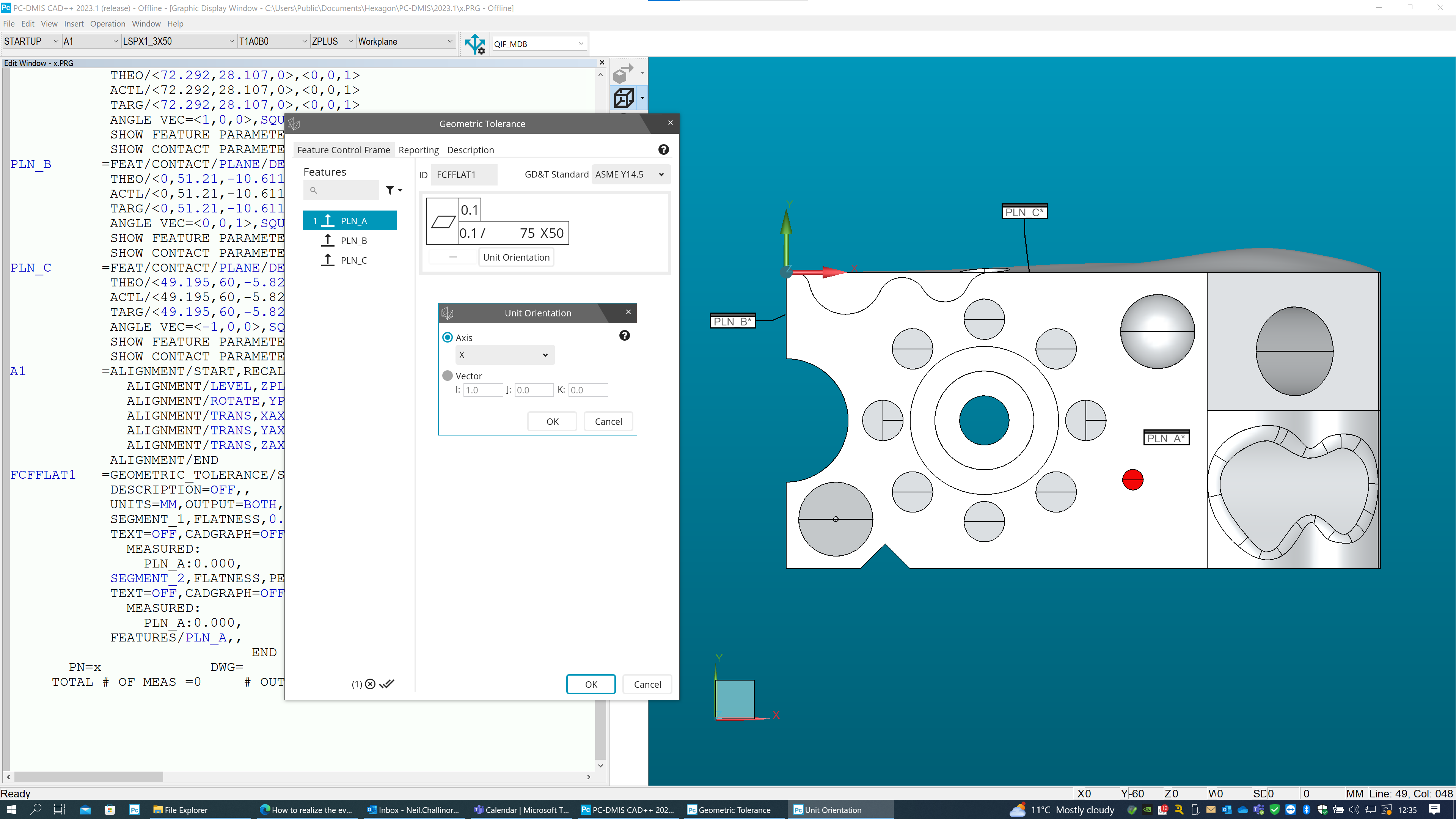
As other people have already explained, the orientation plane modifier controls the tolerance zone orientation. In this case you have a per-unit flatness over a 75x50 rectangular area. The orientation modifier is stipulating that this 75x50 rectangular area needs to be orientated with the longest side of the rectangle parallel to datum C. To achieve this in PC-DMIS, you need to create an alignment and then set the unit orientation accordingly - see my example below...
PLN_A =FEAT/CONTACT/PLANE/DEFAULT,CARTESIAN,NONE,LEAST_SQR
THEO/<72.292,28.107,0>,<0,0,1>
ACTL/<72.292,28.107,0>,<0,0,1>
TARG/<72.292,28.107,0>,<0,0,1>
ANGLE VEC=<1,0,0>,SQUARE
SHOW FEATURE PARAMETERS=NO
SHOW CONTACT PARAMETERS=NO
PLN_B =FEAT/CONTACT/PLANE/DEFAULT,CARTESIAN,NONE,LEAST_SQR
THEO/<0,51.21,-10.611>,<-1,0,0>
ACTL/<0,51.21,-10.611>,<-1,0,0>
TARG/<0,51.21,-10.611>,<-1,0,0>
ANGLE VEC=<0,0,1>,SQUARE
SHOW FEATURE PARAMETERS=NO
SHOW CONTACT PARAMETERS=NO
PLN_C =FEAT/CONTACT/PLANE/DEFAULT,CARTESIAN,NONE,LEAST_SQR
THEO/<49.195,60,-5.825>,<0,1,0>
ACTL/<49.195,60,-5.825>,<0,1,0>
TARG/<49.195,60,-5.825>,<0,1,0>
ANGLE VEC=<-1,0,0>,SQUARE
SHOW FEATURE PARAMETERS=NO
SHOW CONTACT PARAMETERS=NO
A1 =ALIGNMENT/START,RECALL:STARTUP,LIST=YES
ALIGNMENT/LEVEL,ZPLUS,PLN_A
ALIGNMENT/ROTATE,YPLUS,TO,PLN_C,ABOUT,ZPLUS
ALIGNMENT/TRANS,XAXIS,PLN_B
ALIGNMENT/TRANS,YAXIS,PLN_C
ALIGNMENT/TRANS,ZAXIS,PLN_A
ALIGNMENT/END
FCFFLAT1 =GEOMETRIC_TOLERANCE/STANDARD=ASME Y14.5,SHOWEXPANDED=YES,
DESCRIPTION=OFF,,
UNITS=MM,OUTPUT=BOTH,ARROWDENSITY=100,
SEGMENT_1,FLATNESS,0.1,TOL_ZONE_MATH=DEFAULT,
TEXT=OFF,CADGRAPH=OFF,REPORTGRAPH=OFF,MULT=10,
MEASURED:
PLN_A:0.000,
SEGMENT_2,FLATNESS,PER_UNIT,0.1,<UA>,75,50,<1,0,0>, <- (this sets the orientation of the 75mm long edge so that it is running along the X-axis)
TEXT=OFF,CADGRAPH=OFF,REPORTGRAPH=OFF,MULT=10,
MEASURED:
PLN_A:0.000,
FEATURES/PLN_A,,
NOTE: PC-Dmis does not support a per-unit flatness on it's own, we only support the per-unit aspect as a refinement of a general flatness tolerance which is why my example shows two segments - the per-unit is the lower segment.