hexagon logo

Analysis view question


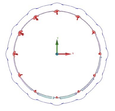
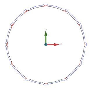
​So long story short, I've never used the analysis views. My question is the does the boundary automatically project to the tolerance limit based on the cad/dimensions or is there a setting that needs input to define the profile tolerance. Management has questioned the zone that's being projected on the report and I'm uncertain of the answer. The main concern is the vectors are going both directions. This coupled with production having exhausted all the test parts they have and need to know how much to offset the profile pattern. I'm running 2019 R1 on a global green with a Leitz Scanning head.
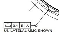
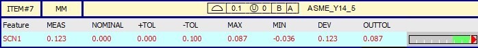
I believe they have an issue with the machining process of the pattern. Any input is appreciated. I'm not impressed with the FCF note either, but I can interpreted the intent at least.

Parents
  • The profile is set to what the FCF should be based on the note of the MMC condition and was confirmed by management, After running the program again the projected zone seems to have "snapped" to the feature. I'll still be looking for a way to communicate what adjustments need to be made as production is asking me how much they need to offset the mill. I personally think the features need to be offset in the CNC program and the min max on the report should indicate how much to adjust the offsets...

  • If the FORM_ONLY for the profile looks good but you have area's going out of tolerance, then using position reporting might aide the operator in the shift required to improve the data analysis. If the FORM_ONLY is bad itself, then the whole path needs to be reviewed by your NC programmer.
Reply Children
No Data