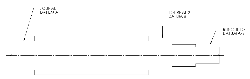
I measured three separate circles for each journal, constructed cast points at each circle and then used those points to construct a line. I leveled to this line.
My question is, can I set this line to Datum A-B for measuring runouts or do I need to make the actual journal cylinders datum A-B for runouts. Attached is a little sketch.
Thanks in advance.