I have a cylinder I'm measuring, (should be a profile in my opinion), that I'm measuring the beginning, middle and end of with 7 points each. This is only 100° of a cylinder. 0.5" long. It is parallel in Z to my a plane. Anyway, my concern is that when I report out each circle constructed least square from the cylinder hits, They are showing a z value of around 0.002" and some change. When I report the cylinder itself it is showing only 0.001" in Z. I report these out in legacy and get the same as well. Why am I 0.001" off. I'd think that the cylinder would be a centroid location which would be an average of the 3 circles used to make the cylinder. Am I missing something?
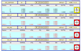
The nominal Z value for your cylinder is 0.0001 different than your circles (CYL1 = 0.3425, CIR25-1, CIR25-2 & CIR25-3 all = 0.03424). Taking that into account, you can see that the Geometric Tolerance command is reporting the worst end of the axis and correlates with CIR25-3.
I did see the difference in nominals after posting which I changed. But that didn't do anything. This still doesn't explain to me why the cylinder as a whole, with no projection, just measuring the whole cylinder (minus .002 from each end) has a true position by half of what each constructed circle is reading. It would make sense if my cylinder had a true postion of .004 (best case) or .0046 (worst case), or .0042 (average) or anywhere in between all of that. It doesn't make sense why it is 0.0021.
Can you share the routine? I won't be able to look at it until Monday but I'm sure I'll be able to explain what's happening if I can look at everything more closely.
yes, let me investigate a little more and get back to you. I just ran a second part and that one averaged out correctly. Checking the alignments to make sure they are robust.
neil.challinor, I gave up on the program and started from scratch. Everything seems to be working correctly now. I had some planes and widths I was using for alignments, but didn't think that would make any difference. But every time I took the part off and put it back on I was getting different results. Sometimes they would be good and sometimes they wouldn't make sense as far as the results. If my memory serves me correct, I think I've seen this before. Maybe modifying a program too much starts messing with some settings deep within. Anyway, I'm all set for now but If you'd like to look at my original program I was having problems with to see if you can see what's going on with the calculations, that would be great and possibly a learning lesson I could show everyone if I in fact did make a mistake. Could I just send the (.prg) to your email?