hexagon logo

Double Secondary Datums in FCF??

Hi All -
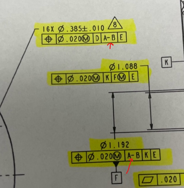
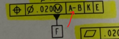
Came across this FCF earlier today and was wondering how to enter this into the FCF within my Program??
It allows me to choose A or B, but not both under the secondary datum (Or Primary Datum as shown further down in the photo)... Any help would be greatly appreciated. Thanks!!
  • assuming it's 2 bores that share the same axis centerline, you can connect the two features and use that.
    PCDMIS will allow you to label a datum with 2 letters.
  • It's probably a center-line between 2 circles
  • Define each datum feature as a datum using the DATDEF command. In your geometric tolerance dialog window, create a new datum reference, select the common datum checkbox, and choose the two previously defined datums.

    If you're using XactMeasure, define the two datums (individually) using the DATDEF command. Type A-B in the datum reference frame.
  • Perfect, thanks guys. It was the center line of 2 circles. I constructed said center line, assigned as Datum "AB" and now I'm off to the races once again.
    Appreciate all of your quick feedback!


  • Hmm never seen that before. The help explanation is a bit confusing to me. Multiple times have I used a cylinder as a primary Datum. Isn't this a good practice in PC-Dmis?


  • Hmm never seen that before. The help explanation is a bit confusing to me. Multiple times have I used a cylinder as a primary Datum. Isn't this a good practice in PC-Dmis?


    A cylinder is fine, it is lines that you should be wary of. Technically, there is no such thing as a line - it is either an axis of revolution (cone or cylinder axis for example) or a linear cross section of a planar surface. Obliviously, as CMM programmers, we use lines all the time and have become accustomed to having to create constructed features of various types in order to work around software limitations and apply what we think is the correct design intent. The Geometric Tolerance command requires a different way of thinking and working which greatly simplifies things. Constructed features are generally not needed and can actually hinder the way the Geometric Tolerance command is designed to work because they obscure access to the hit data. Rather than relying on the user to interpret design intent and create constructions and alignments, the Geometric Tolerance command simply requires you to supply hit data and build the feature control frame - it handles the rest. The best way to ensure you are supplying good hit data is to measure simple features (auto-features, measured features and scans).

    To come back to your question about using a cylinder and why that differs from a line, the distinction I'm making is that the line only represents the axis, a cylinder represents the surface as well. The Geometric Tolerance command simulates hard-gauging and requires surface data. The accuracy of the result and how closely that result will correlate with an actual hard gauge check is dependent on how much of the surface you have probed and supplied data for.
  • , This would be the wrong approach if you're using the Geometric Tolerance command. You need to do what said.


  • A cylinder is fine, it is lines that you should be wary of. Technically, there is no such thing as a line - it is either an axis of revolution (cone or cylinder axis for example) or a linear cross section of a planar surface. Obliviously, as CMM programmers, we use lines all the time and have become accustomed to having to create constructed features of various types in order to work around software limitations and apply what we think is the correct design intent. The Geometric Tolerance command requires a different way of thinking and working which greatly simplifies things. Constructed features are generally not needed and can actually hinder the way the Geometric Tolerance command is designed to work because they obscure access to the hit data. Rather than relying on the user to interpret design intent and create constructions and alignments, the Geometric Tolerance command simply requires you to supply hit data and build the feature control frame - it handles the rest. The best way to ensure you are supplying good hit data is to measure simple features (auto-features, measured features and scans).

    To come back to your question about using a cylinder and why that differs from a line, the distinction I'm making is that the line only represents the axis, a cylinder represents the surface as well. The Geometric Tolerance command simulates hard-gauging and requires surface data. The accuracy of the result and how closely that result will correlate with an actual hard gauge check is dependent on how much of the surface you have probed and supplied data for.


    To be more specific with OP's callout... for the following callout:

    Assuming 3 scenarios, one where he is constructing a cylinder from 2 auto-cylinders, one where he is taking a sole auto-cylinder at the 2 ends of the part (same T points and vectors obviously as case 1) and finally constructing a line from the cylinders in case 1. From what I get, scenario 3 should not be used as a primary datum and logic says scenario 2 is better than scenario 1, all in terms of how PC-Dmis calculates the results. Is this correct?