hexagon logo

Need help with the function "scan minimum" when creating a circle

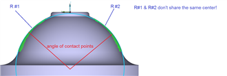
I have a part an where I need to measure a contact angle of a circle contacting 2 other circles as well as the radii of these 2 other circles.


At the moment I use 3 scans to achieve this.
  1. One scan to evaluate the radius #1 (just the left side)
  2. One scan to evaluate the radius #2 (just the right side)
  3. One scan from left to right (over the top surface) to generate a contact circle which contacts a point left and right each to calculate the contact angle. I use the function "scan minimum" to create the contact circle.
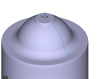
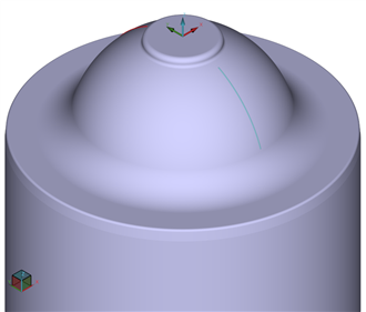
One problem I have, is that the scans are a bit rough/jittery. This results in the contact angle not being very stable.

What I want to do now is the following:
  • get rid of the third scan from left to right
  • filter the two separate radius scans
  • generate the contact circle from the two filtered scans

The problem is, that the feature "scan minimum" doesn't allow me to input 2 separate scans.
I tried to generate a a set of the two scans and a point cloud to get around this limitation but nothing works.

Does somebody knows a way to get around this limitation? Maybe there is a way to feed all the pints into one scan?
If possible I would prefer a solution without a script but if necessary I would also resort to a script.
Parents


  • Thank you for this Idea! It's not ideal for us as it completely eliminates any form error... but it's the best that I can do at the moment.

    I had to make some adjustment though:
    - Measure the two circles
    - Create a 'Z' Vector line with X,Y set as zero (centre of part)
    - Set a local Alignment centred on one of the measured circles
    - Create a generic circle X,Y,Z set Zero, with a radius calculated by subtracting the theoretical contact circles RADIUS
    as example CIR1.R.MEAS-20 set this for both nominal and measured
    - Construct a pierce point between the generic circle and the 'Z' vector line, you may need to reverse the line to get correct point
    - Construct a midpoint from the 2 pierce points (left and right) as they can vary a bit
    - Construct a line from each measured circle to the mid point

    I'm still verifying to test if this gets me the correct result but so far it looks good!
    After measuring the part 10 times I got the Range down from 2.3° to 0.3°! Slight smile
Reply


  • Thank you for this Idea! It's not ideal for us as it completely eliminates any form error... but it's the best that I can do at the moment.

    I had to make some adjustment though:
    - Measure the two circles
    - Create a 'Z' Vector line with X,Y set as zero (centre of part)
    - Set a local Alignment centred on one of the measured circles
    - Create a generic circle X,Y,Z set Zero, with a radius calculated by subtracting the theoretical contact circles RADIUS
    as example CIR1.R.MEAS-20 set this for both nominal and measured
    - Construct a pierce point between the generic circle and the 'Z' vector line, you may need to reverse the line to get correct point
    - Construct a midpoint from the 2 pierce points (left and right) as they can vary a bit
    - Construct a line from each measured circle to the mid point

    I'm still verifying to test if this gets me the correct result but so far it looks good!
    After measuring the part 10 times I got the Range down from 2.3° to 0.3°! Slight smile
Children
No Data