hexagon logo

I need help with measuring distance at an angle.


Hello everyone,
I need advice...
The operator says that the parts are good, the angle is perfect (20 degrees), I get a different result on the CMM after measuring.
Am I making some mistake? I only have one year of experience...
I don't like CON1 (position on the x-axis). CON1 is made up of 8 points to see only the average of the angle and i location (print doesn't call out)).
I would like to add codes but i don't know how to do it...
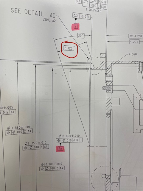
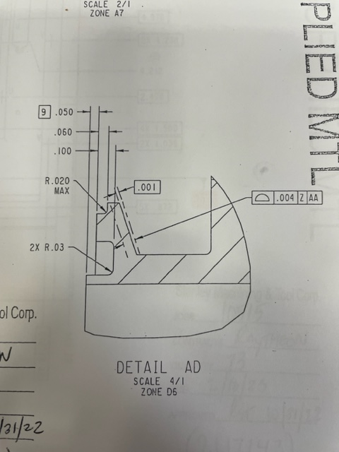


 ​​​

This is how i created:

WORKPLANE/ZPLUS
MOVE/POINT,NORMAL,<17.88762,5.57913,-0.19795>
TIP/T1A90B90, SHANKIJK=0.99979, -0.02011, -0.00449, ANGLE=-90.78014
PNT14 =FEAT/CONTACT/VECTOR POINT/DEFAULT,CARTESIAN
THEO/<5.64,0,-0.225>,<0.3420223,0,-0.9396918>
ACTL/<5.63419,0.00011,-0.20894>,<0.3420223,0,-0.9396918>
TARG/<5.64,0,-0.225>,<0.3420223,0,-0.9396918>
SNAP=NO
SHOW FEATURE PARAMETERS=NO
SHOW CONTACT PARAMETERS=YES
AVOIDANCE MOVE=NO
SHOW HITS=YES
HIT/BASIC,<5.64,0,-0.225>,<0.3420223,0,-0.9396918>,<5.64,0,-0.225>
ENDMEAS/
PNT15 =FEAT/CONTACT/VECTOR POINT/DEFAULT,CARTESIAN
THEO/<5.8,0,-0.18>,<0.3420223,0,-0.9396918>
ACTL/<5.78983,0.00012,-0.15185>,<0.3420223,0,-0.9396918>
TARG/<5.8,0,-0.18>,<0.3420223,0,-0.9396918>
SNAP=NO
SHOW FEATURE PARAMETERS=NO
SHOW CONTACT PARAMETERS=YES
AVOIDANCE MOVE=NO
SHOW HITS=YES
HIT/BASIC,<5.8,0,-0.18>,<0.3420223,0,-0.9396918>,<5.8,0,-0.18>
ENDMEAS/
LIN4 =FEAT/LINE,CARTESIAN,UNBOUNDED,NO
THEO/<5.80559,0,-0.1782>,<-0.9626509,0,-0.2707456>
ACTL/<5.78964,0.00012,-0.15191>,<-0.9388199,-0.000083,-0.3444084>
CONSTR/LINE,BFRE,3D,PNT15,PNT14,,
OUTLIER_REMOVAL/OFF,3
FILTER/OFF,WAVELENGTH=0
WORKPLANE/YMINUS
DIM ANGL3= 2D ANGLE TO LINE LIN4 FROM XAXIS ,$
GRAPH=OFF TEXT=OFF MULT=1.00 OUTPUT=BOTH
AX NOMINAL +TOL -TOL MEAS DEV OUTTOL
A 20.00000 0.00000 0.00000 20.14569 0.14569 0.14569 -------->​

A5 =ALIGNMENT/START,RECALL:STARTUP,LIST=YES
ALIGNMENT/LEVEL,ZPLUS,PLN2_Z
ALIGNMENT/ROTATE_CIRCLE,YMINUS,TO,CYL1_AA,AND,PNT2,ABOUT,ZPL US
ALIGNMENT/TRANS,ZAXIS,PLN2_Z
ALIGNMENT/TRANS,XAXIS,CYL1_AA
ALIGNMENT/TRANS,YAXIS,CYL1_AA
ALIGNMENT/ROTATE_OFFSET,-20,ABOUT,YPLUS
ALIGNMENT/END
WORKPLANE/XPLUS
PLN4 =FEAT/PLANE,CARTESIAN,OUTLINE,NO
THEO/<0,0,0>,<1,0,0>
ACTL/<0,0,0>,<1,0,0>
CONSTR/PLANE,ALIGN,WORKPLANE
PNT11 =FEAT/POINT,CARTESIAN,NO
THEO/<0,0,-1.74828>,<-0.9971964,0,0.0748284>
ACTL/<0,-0.00032,-2.13663>,<-0.9999968,-0.000083,-0.0025427>
CONSTR/POINT,PIERCE,PLN4,LIN4
DIM LOC4_LIN4= LOCATION OF POINT PNT11 UNITS=IN ,$
GRAPH=OFF TEXT=OFF MULT=1.00 OUTPUT=BOTH HALF ANGLE=NO
AX NOMINAL +TOL -TOL MEAS DEV OUTTOL
X 0.00000 0.01969 0.01969 0.00000 0.00000 0.00000 ----#----
Y 0.00000 0.01969 0.01969 -0.00032 -0.00032 0.00000 ----#----
Z -2.12000 0.00200 0.00200 -2.13663 -0.01663 0.01463 <--------
END OF DIMENSION LOC4_LIN4​

Attached Files
Parents
  • Here's my take. Your part is cylindrical in shape, yes? Then your profile of that surface in detail D is essentially measuring a CONE, as defined by the angle and basic offset (angle A and side b known).
    If it were me:
    I would datum to the center of the part, rotate so you have a securely controlled 6DOF alignment to the part in some way.

    Start copy/paste with pattern segment:
    Then align/rotate +20° about X axis (presuming Z is your cylindrical part axis). Make sure it tilts the correct way!
    Within that same alignment window offset Z the -2.120". Again confirm polarity here, you want tetrahedron to look parallel to the conical section in detail D, not 2" the other way lol.
    -Then measure a tiny line-section of that cone with as many hits as you can (or if you want to K.I.S.S. run an array of individual probe points along the line).
    --All hits should have normal Z vector and z coordinate nominal of zero.--
    Recall alignment back to original datums.
    End copy/paste with pattern segment:

    -Copy paste the above segment of code with pattern 3x (to make 4x 90° section cuts of the cone sampled), 5x (to make 6x 60° cuts) 11x (a dozen 30° cuts)... whatever you feel is necessary to affirm the profile is within spec.
    You will likely need to manually create define and adjust probe angles for some of the pasted pattern to access the surfaces (hence why i didn't suggest to loop it)... but you will end up with a series of section cuts of the cone.
    -Construct a measured cone from the lines. You might need to "explode" the lines into individual hit values before the measured cone is a successful representation of the part.
    ​-Dimension the measured cone.

    The measured value of the angle isn't necessary to quantify, nor is the measured value of the basic offset. you just need to quantify the MAX+MIN profile variation from the theoretical exact location.
Reply
  • Here's my take. Your part is cylindrical in shape, yes? Then your profile of that surface in detail D is essentially measuring a CONE, as defined by the angle and basic offset (angle A and side b known).
    If it were me:
    I would datum to the center of the part, rotate so you have a securely controlled 6DOF alignment to the part in some way.

    Start copy/paste with pattern segment:
    Then align/rotate +20° about X axis (presuming Z is your cylindrical part axis). Make sure it tilts the correct way!
    Within that same alignment window offset Z the -2.120". Again confirm polarity here, you want tetrahedron to look parallel to the conical section in detail D, not 2" the other way lol.
    -Then measure a tiny line-section of that cone with as many hits as you can (or if you want to K.I.S.S. run an array of individual probe points along the line).
    --All hits should have normal Z vector and z coordinate nominal of zero.--
    Recall alignment back to original datums.
    End copy/paste with pattern segment:

    -Copy paste the above segment of code with pattern 3x (to make 4x 90° section cuts of the cone sampled), 5x (to make 6x 60° cuts) 11x (a dozen 30° cuts)... whatever you feel is necessary to affirm the profile is within spec.
    You will likely need to manually create define and adjust probe angles for some of the pasted pattern to access the surfaces (hence why i didn't suggest to loop it)... but you will end up with a series of section cuts of the cone.
    -Construct a measured cone from the lines. You might need to "explode" the lines into individual hit values before the measured cone is a successful representation of the part.
    ​-Dimension the measured cone.

    The measured value of the angle isn't necessary to quantify, nor is the measured value of the basic offset. you just need to quantify the MAX+MIN profile variation from the theoretical exact location.
Children
No Data