
Hello everyone,
I need advice...
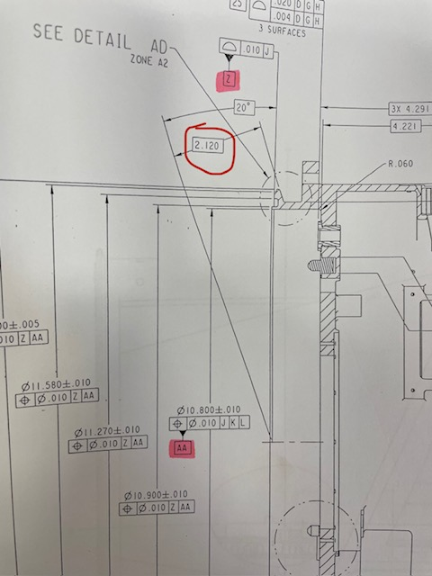
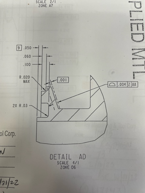
The operator says that the parts are good, the angle is perfect (20 degrees), I get a different result on the CMM after measuring.
Am I making some mistake? I only have one year of experience...
I don't like CON1 (position on the x-axis). CON1 is made up of 8 points to see only the average of the angle and i location (print doesn't call out)).
I would like to add codes but i don't know how to do it...
This is how i created:
WORKPLANE/ZPLUS
MOVE/POINT,NORMAL,<17.88762,5.57913,-0.19795>
TIP/T1A90B90, SHANKIJK=0.99979, -0.02011, -0.00449, ANGLE=-90.78014
PNT14 =FEAT/CONTACT/VECTOR POINT/DEFAULT,CARTESIAN
THEO/<5.64,0,-0.225>,<0.3420223,0,-0.9396918>
ACTL/<5.63419,0.00011,-0.20894>,<0.3420223,0,-0.9396918>
TARG/<5.64,0,-0.225>,<0.3420223,0,-0.9396918>
SNAP=NO
SHOW FEATURE PARAMETERS=NO
SHOW CONTACT PARAMETERS=YES
AVOIDANCE MOVE=NO
SHOW HITS=YES
HIT/BASIC,<5.64,0,-0.225>,<0.3420223,0,-0.9396918>,<5.64,0,-0.225>
ENDMEAS/
PNT15 =FEAT/CONTACT/VECTOR POINT/DEFAULT,CARTESIAN
THEO/<5.8,0,-0.18>,<0.3420223,0,-0.9396918>
ACTL/<5.78983,0.00012,-0.15185>,<0.3420223,0,-0.9396918>
TARG/<5.8,0,-0.18>,<0.3420223,0,-0.9396918>
SNAP=NO
SHOW FEATURE PARAMETERS=NO
SHOW CONTACT PARAMETERS=YES
AVOIDANCE MOVE=NO
SHOW HITS=YES
HIT/BASIC,<5.8,0,-0.18>,<0.3420223,0,-0.9396918>,<5.8,0,-0.18>
ENDMEAS/
LIN4 =FEAT/LINE,CARTESIAN,UNBOUNDED,NO
THEO/<5.80559,0,-0.1782>,<-0.9626509,0,-0.2707456>
ACTL/<5.78964,0.00012,-0.15191>,<-0.9388199,-0.000083,-0.3444084>
CONSTR/LINE,BFRE,3D,PNT15,PNT14,,
OUTLIER_REMOVAL/OFF,3
FILTER/OFF,WAVELENGTH=0
WORKPLANE/YMINUS
DIM ANGL3= 2D ANGLE TO LINE LIN4 FROM XAXIS ,$
GRAPH=OFF TEXT=OFF MULT=1.00 OUTPUT=BOTH
AX NOMINAL +TOL -TOL MEAS DEV OUTTOL
A 20.00000 0.00000 0.00000 20.14569 0.14569 0.14569 -------->
A5 =ALIGNMENT/START,RECALL:STARTUP,LIST=YES
ALIGNMENT/LEVEL,ZPLUS,PLN2_Z
ALIGNMENT/ROTATE_CIRCLE,YMINUS,TO,CYL1_AA,AND,PNT2,ABOUT,ZPL US
ALIGNMENT/TRANS,ZAXIS,PLN2_Z
ALIGNMENT/TRANS,XAXIS,CYL1_AA
ALIGNMENT/TRANS,YAXIS,CYL1_AA
ALIGNMENT/ROTATE_OFFSET,-20,ABOUT,YPLUS
ALIGNMENT/END
WORKPLANE/XPLUS
PLN4 =FEAT/PLANE,CARTESIAN,OUTLINE,NO
THEO/<0,0,0>,<1,0,0>
ACTL/<0,0,0>,<1,0,0>
CONSTR/PLANE,ALIGN,WORKPLANE
PNT11 =FEAT/POINT,CARTESIAN,NO
THEO/<0,0,-1.74828>,<-0.9971964,0,0.0748284>
ACTL/<0,-0.00032,-2.13663>,<-0.9999968,-0.000083,-0.0025427>
CONSTR/POINT,PIERCE,PLN4,LIN4
DIM LOC4_LIN4= LOCATION OF POINT PNT11 UNITS=IN ,$
GRAPH=OFF TEXT=OFF MULT=1.00 OUTPUT=BOTH HALF ANGLE=NO
AX NOMINAL +TOL -TOL MEAS DEV OUTTOL
X 0.00000 0.01969 0.01969 0.00000 0.00000 0.00000 ----#----
Y 0.00000 0.01969 0.01969 -0.00032 -0.00032 0.00000 ----#----
Z -2.12000 0.00200 0.00200 -2.13663 -0.01663 0.01463 <--------
END OF DIMENSION LOC4_LIN4
Attached Files
