If your CAD part has its z zero on the bottom, which coincides with the granite surface of the CMM, How do you take hits on that surface in DCC mode? In manual mode its simple to probe the granite around the part and call that z zero. Once you switch to DCC mode, I cant figure out a way to instruct the machine to take hits on a plane extended out from the part bottom. I have worked around this in the past by moving the z on the cad model but the part I am measuring now doesn't lend itself to that method. It is basically a large cone with no plane at the top. The part is too large to fixture on its side. Thanks in advance.
Edited to reflect that you don't have a bottom plane.
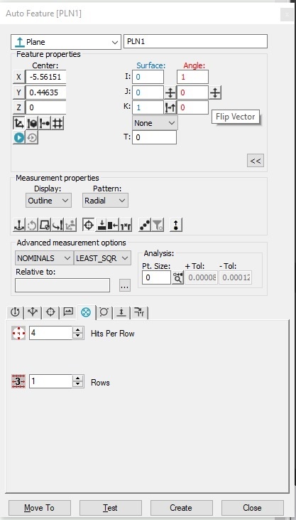
If you have an alignment still relative to the machine, all you need to do is change the XYZ values to match theoretically the coordinate values where the granite is located. make sure your surface vector is positive 1 in Z and you should be set (you can flip surface vector or angle vector (which defines start hit rotationally about part) by clicking those up/down arrow buttons to the right of each set (per below snip). You can also fiddle with x and y values to shift the center of the patterned points
Your hit pattern and distance are the only other knobs to mess with, to reflect a larger plane than your sample part.
Voila autofeature on your granite.
As for using CMM granite as a surface plate:
Historically when I worked at Honeywell (going back to the early 2000's) our B&S Global Advantage had granite cleaned and calibrated annually, to be within flatness spec of A-Grade surface plate... We often used it for just that. It's definitely possible to use the top surface of a CMM as a reference plane (surface plate).
--However, if your granite isn't independently calibrated, you are technically at-risk of adding uncertainty and conformance issues when making lot acceptance decisions. use at your discretion, and maybe assess the plate on your own (at a minimum) for flatness, before using it as such.
I'm willing to bet Hexagon does provide some type of statement of granite flatness upon delivery of each machine someplace. Call them up and ask. The worst that will happen is they will leave you where you currently are.
Edited to reflect that you don't have a bottom plane.
If you have an alignment still relative to the machine, all you need to do is change the XYZ values to match theoretically the coordinate values where the granite is located. make sure your surface vector is positive 1 in Z and you should be set (you can flip surface vector or angle vector (which defines start hit rotationally about part) by clicking those up/down arrow buttons to the right of each set (per below snip). You can also fiddle with x and y values to shift the center of the patterned points
Your hit pattern and distance are the only other knobs to mess with, to reflect a larger plane than your sample part.
Voila autofeature on your granite.
As for using CMM granite as a surface plate:
Historically when I worked at Honeywell (going back to the early 2000's) our B&S Global Advantage had granite cleaned and calibrated annually, to be within flatness spec of A-Grade surface plate... We often used it for just that. It's definitely possible to use the top surface of a CMM as a reference plane (surface plate).
--However, if your granite isn't independently calibrated, you are technically at-risk of adding uncertainty and conformance issues when making lot acceptance decisions. use at your discretion, and maybe assess the plate on your own (at a minimum) for flatness, before using it as such.
I'm willing to bet Hexagon does provide some type of statement of granite flatness upon delivery of each machine someplace. Call them up and ask. The worst that will happen is they will leave you where you currently are.