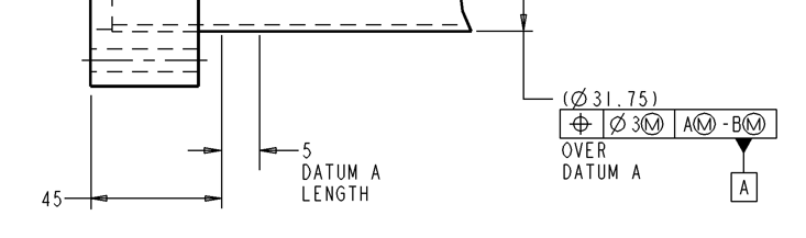
Has anyone seen a FCF like this? Was wondering if it is a universal thing or if it's customer specific. I think I might understand what it's asking, but I'm not sure how to input that into PC DMIS. A and B in the FCF are points on either end of a tube.
This A-B callout creates a common center line between to concentric diameters. What is Datum B? However, what I do not understand is how the FCF calls out MMB on Datum A when it clearly is a reference (no tolerance, unless the diameter size is somewhere else on the print). Plus, the FCF is on A, then calls itself back to itself.
Datum B is the same thing as Datum A, just on the other side of the tube. It's symmetrical, so I don't think it matters which one I define as A or B. I don't want to post the whole print because that's technically not allowed. But there are two defined points on either end of the tube called out as A and B on the print They are two endpoints of the tube's axis. The diameter is on the print, but as a reference dimension. There's no tolerance. I assume I'm supposed to use the stock tolerance, which neither I nor my boss can find. If I'm reading it right, it wants the position of a 5mm length of the tube at both ends compared to the rest of it. Seems like an overly complicated and dumb way to call out the straightness of the entire tube, but I could be wrong.
This customer is also known as "Big Yellow" and they have their own standard that resembles the ASME Y14.5, but has some notable differences. I'm guessing this is one of them.
They are not calling out straightness, they are asking you to measure the position of the Datum A tube at the 5mm zone against the centerline formed between A and B. Since the tube is a reference with no tolerance, just omit the MMB from A and B, and the MMC from the 3 tolerance.
Is there any standard references on the print? Your best bet is to go back to the customer and ask for clarification, in writing.
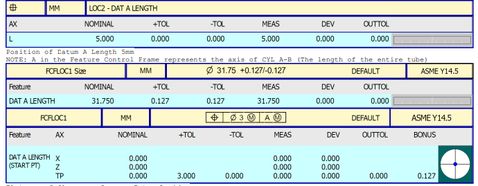
That's what I did, I measured the position of that 5mm length to the axis of the entire tube. My boss told me to use the stock tolerance from another similar tube. I don't know how to build that FCF in PC DMIS, so I assigned that axis from A-B as Datum A with a comment that it represents A-B on the print. See below. I didn't know how else to do it. My first PPAP and it had to be a print that I don't really understand .
It doesn't make any sense:
- the FCF is datum A
- the FCF states "over datum A" (?)
- the FCF relates back to datum A (and B)
- we have an indication of where datum A is with a length as well and it is not where the distance and length tells us because the FCF states otherwise
Suggestion: call the designer and have them clarify what the intention of the callout is, maybe then you could do a proper evaluation, not neccessarily the one that is on drawing.
create A, then B open Datum Dialogue and select common datum check box, then select A and then B hit ok. now you have A-B
If I'm understanding the print correctly, A-B on the print is the center line between two concentric circles measured at the extreme ends of the tube. So to get those points, I believe I have to measure the inside diameters at both ends, measure the ends of the tube as planes, and construct projection points from the IDs and the planes at each end to give me points A and B that are called out on the print. I assigned those points as Datums A and B, then created a common datum. So yes, now I have Datum A-B. Problem is, PCDMIS won't let me use that as a primary datum in a FCF because it only allows common datums from 3D features to be used as primary datums. I could assign those two previously mentioned planes as Datums A and B, and then it will let me use common Datum A-B as a primary datum, but that's not how the print calls it out. So I don't know where to go from here. I could be misinterpreting this or overthinking it.
You might have better luck constructing a 3d line between the points and using that line as A-B for the primary, leveling datum and setting 2 axes' origins.