hexagon logo

Custom Reports - Keep the view in the Objects

Hi guys

I have asked Hexagon for help, but the answer and tips I got from them doesn’t seem to work for me.
So now I hope that one of you have been in the same situation as I am in and have a “step-by-step” guide that can help me.

The situation:
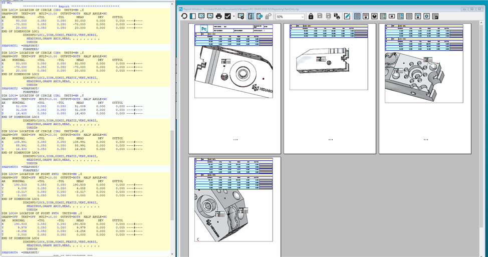
I have some programs made by Hexagon that uses ‘Custom Report’.
On every page there is a “screen-shots” of the areas of the part, to which the results on the same page refer.
Everything is fine, until now.
My colleagues in the production would like me to make a new layout.
They would like to make it easier for the operators to read the report. I agree, it’s actually a good idea.

So, on the report, they would like the results divided into “chapters” like this:
  1. Alignment. It is an iterative alignment, and this shows that the alignment is okay.
  2. Distances to CNC-fixture. This will help the CNC-technicians adjust the part in the fixtures.
  3. All dimensions of machined features: Positions of holes and slots. Diameter of holes. Length and width of slots. Depth of holes and slots.
  4. Positions of the part. The part is an extruded profile made in aluminum, so the CNC-technicians will be, with help from these information’s, able to position the machined features (holes and slots) correctly on the extruded profile.
I was told by Hexagon, that the “screen-shots” are not allowed to have the same name (ObjectName), so I have renamed them every time I inserted a new “screen-shot”.
After that I inserted the measurement according to the inserted “screen-shot” on every page.
Everything works fine.
BUT…
When I save the ‘Custom Report’, and make a preview of the report, all “screen-shots” are changed compared to the view I made during the editing.
Not one of them looks like they did, when I saved the ‘Custom report’, and when I try to fix it afterwards, the result is the same. They “turn” back, and shows the part from a totally different angle.

I have tried different procedures, because I though it had to do with the order I inserted, renamed the “screen-shots” in. No difference. No matter which order I use, the result is the same.
I looked it up in the manual for “how to make ‘Custom report’ or even ‘Reports at all’.
Could not find a solution.


I’m close to give up and call it a day.
So, you are my last chance of finding the trick to fix this.
I could really use a ‘Step-by’step’ guide on how to fix this issue.

Anyone?
  • I've never been a fan of the way Pcdmis makes visual reports, text reports, fine, but visual? Nope. I do all of mine in Excel. Lots of setup to do it, but they look EXACTLY the same, every time. Sorry I've no help for your problem as a Pcdmis issue, but it's good to know there are other ways of doing it.
  • Excel...
    That sounds interesting.
    My reports are saved as PDF, to lock them so no one can edit them afterwards.

    I'm not happy with the 'Custom Reports' but when Hexagon made them, it was all perfect.
    The troubles starts by editing them. I'm close to run screaming away.
    I simply can't fins a way, or an order on how to get them to stay in "place" from the view I adjust them to.
    It's very frustating.
  • I've not done much as far as adding snapshots to actual reporting, but have you tried changing the snapshot "LIVE" slider off? If you use that.

    I've messed with custom reports a lot lately, so I may be able to figure something out with more info about how you're editing your custom report.
  • I've never been a fan of the way Pcdmis makes visual reports, text reports, fine, but visual? Nope. I do all of mine in Excel. Lots of setup to do it, but they look EXACTLY the same, every time. Sorry I've no help for your problem as a Pcdmis issue, but it's good to know there are other ways of doing it.


    I agree, I am struggling with creating great reports, a breeze in software like Zeiss Inspect but a nightmare in PC-DMIS.

    Sometimes you need to have an evaluation before the snapshot in order for the snapshot to show up on the report.

    Modus operandi is:
    Create everything that you want to be shown in the snapshot.
    Create view.
    Recall the view you created.
    Create snapshot.
  • What I have found to reduce some of the issues with the PC-DMIS reports is to use the Text and Cad Report. With the Text and Cad Report I will adjust the cad views and use the Label Layout Wizard when needed to create the report. Then I will execute the measurement routine offline and save the PDF report as Dimension Feature Locations. Now I can use the Dimension Features Location PDF for any report output that I will use. Except when a customer is requesting a specific PC-DMIS Report.
  • Are you using Viewsets before the snapshot? For my reports, I will get the CAD in the position I want, then create a "Viewset", and then recall that viewset, then snapshot. Then each snapshot will show in their specific viewset each time.

    I hope that helps, not sure if this is what you are trying to accomplish though.
  • Hi Guys.

    Thanks for all input so far.
    I can read from your replies that I wasn’t clear enough in my cry for help.


    When I use TextOnly Reports I use the screenshot (Viewset). Just as ANDHERO is describing.
    But when using this option, I can’t add the Dimensions and let them point to the actual data, that I want to present to the operator.


    That is the reason why Hexagon made the reports as ’Custom Report’.
    In ’Custom Report’, they have inserted a ’CadReportObject’, along with some ’Dimensininfo’-boxes to the page, and all together it shows the operator where the Vector Points are taken.
    As long all dimensions are green, no one notice it.
    But if they turn red or yellow, it’s nice to know where they are, so the right actions can be taken.

    On the ‘Custom report’, the ’CadReportObject’ is a “picture” of the part frozen in a view, that allows me to turn the part around, showing exact the details, that I want the operator to focus on.

    And this ’CadReportObject’ is what I was referring to as a ’screen-shot’.
    And it’s the reason for my posting, as the “picture” changes the viewpoint, from the time I add it, and adjust it and to I save the report.
    Because when I look at the report after having saved it, the viewpoint from where I took the “picture” has changed, and it seems to be out of control. At least out of my control.

    Ex.
    I show one end of a profile, and ad 4 dimensions showing every corner.
    When looking at the report (Preview), the part is turned upside down, and the ‘Leader Lines’ are pointing to the opposite end of the part, hidden for the operator.
    So actually, not the help it was supposed to be, but more confusing.


    This is how I "design" my view:

    If you look at the attached files,
    Endview - A - Before.jpg
    is how it looked as was designing it.

    Endview - B - After.jpg
    This shows the report after I have saved the layout in 'Custom Report'.

    Attached Files
  • Doesn't the snapshot button do all of this?

    I have used it with clip planes and everything to show inside of parts with only the relevant dimension info shown? Doesn't always work great with CAD graphics on dimensions but I think as @ ​ said its an order of operations thing.

    Here is a lil clip showing it. No view sets, no magic other than showing/hiding things before you hit the snapshot button. I'm running 2020R2 I believe they updated the snapshots in later versions and in that case I think there is a liveview setting or something that changes how its displayed.

     ​​

    Attached Files
  • Sorry, the snapshot feature works kind of fine, but according to the help file, for every pagefeed you do in the program, a new page should be generated if you use the CADReport - this does not happen for me. I must add an evaluation in order for the new page with a new CAD object to appear. I couldn't edit my original post...