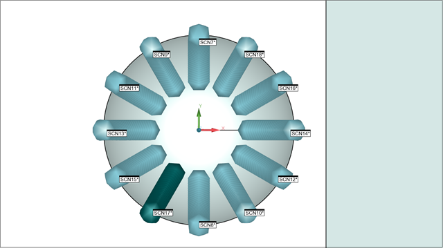
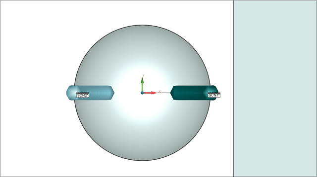
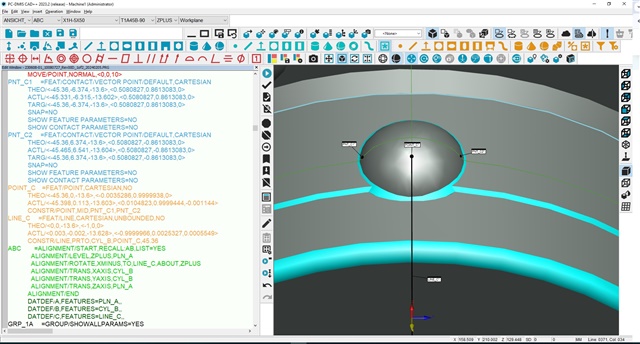
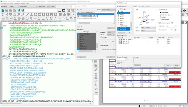
Using PCDMIS 2023.2 Build #212 (service Pack 3), Analog Probe with a 5 by 50 probe .
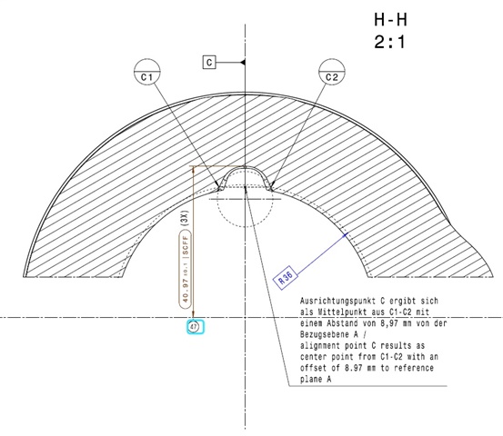
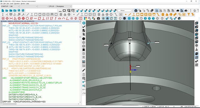
After getting Datums A and B on A0B0 rotate to A45B-90 to get Datum C points, construct Midpoint C then Line C from Cylinder B perpendicular to Midpoint C. ABC Alignment is Level A Zplus, Rotate Xminus to Line C, Origin XY Datum B, Origin Z Datum A.
Datum A (Adaptive Plane Circle Scan) 2 Rings, Datum B (Adaptive Cylinder Spiral Scan), Datum C (midpoint of C1-C2 at X45.36 Z-13.6).
Sphere is measured with 17 points A45B-90 to report Z,PR,PA,D,RN to help machinist understand sphere area. After inserting a clip plane at 0,0,-13.6,0,0,1 and Create Section Cut Curves, insert Linear Open Scan on Left and Right 30º individual surface and a second clip plane at 0,0,0,0,1,0 to insert Linear Open Scan on Top and Bottom 25.5º individual surface. Repeat same process for 2 more half spheres.
Discussions we have had in reference to reporting Profile of a Surface or Profile of a Line, in the end it shows the same deviation. So, any suggestions on how I can improve this half sphere and 4 surfaces?
Thank you in advance.

