hexagon logo

Profile of a Surface - 4 areas of half sphere

Using PCDMIS 2023.2 Build #212 (service Pack 3), Analog Probe with a 5 by 50 probe .

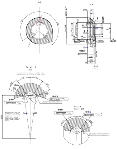
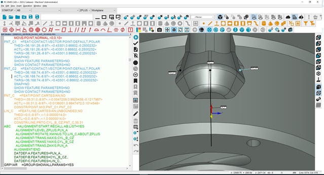
After getting Datums A and B on A0B0 rotate to A45B-90 to get Datum C points, construct Midpoint C then Line C from Cylinder B perpendicular to Midpoint C. ABC Alignment is Level A Zplus, Rotate Xminus to Line C, Origin XY Datum B, Origin Z Datum A.

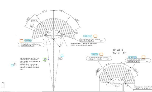
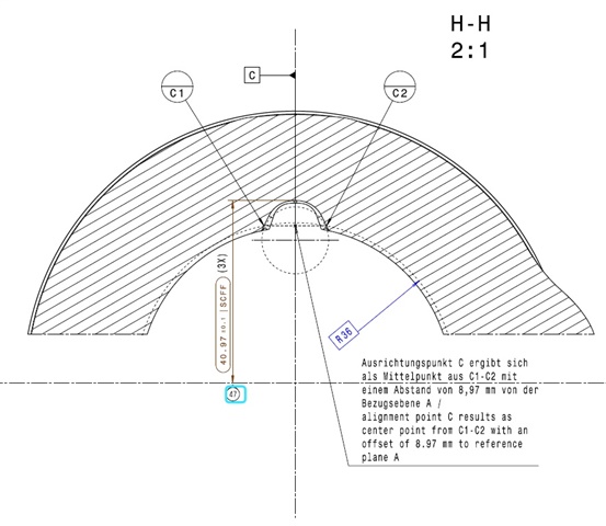
Datum A (Adaptive Plane Circle Scan) 2 Rings, Datum B (Adaptive Cylinder Spiral Scan), Datum C (midpoint of C1-C2 at X45.36 Z-13.6).

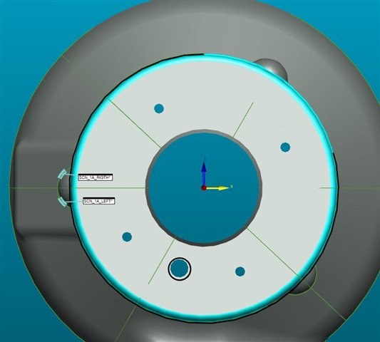
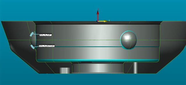
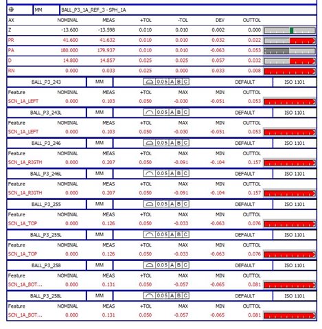
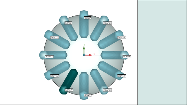
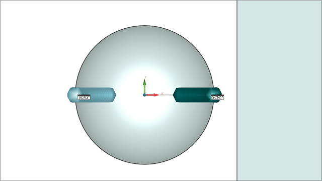
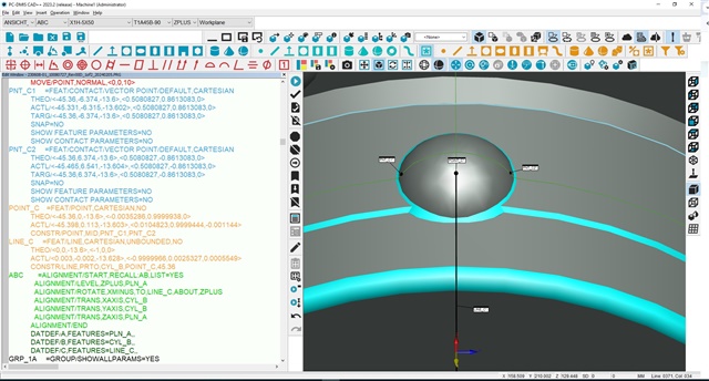
Sphere is measured with 17 points A45B-90 to report Z,PR,PA,D,RN to help machinist understand sphere area. After inserting a clip plane at 0,0,-13.6,0,0,1 and Create Section Cut Curves, insert Linear Open Scan on Left and Right 30º individual surface and a second clip plane at 0,0,0,0,1,0 to insert Linear Open Scan on Top and Bottom 25.5º individual surface. Repeat same process for 2 more half spheres.

Discussions we have had in reference to reporting Profile of a Surface or Profile of a Line, in the end it shows the same deviation. So, any suggestions on how I can improve this half sphere and 4 surfaces?

Thank you in advance.

Parents
  • What do you mean by "perpendicular to mid point" ?

    In your case, I would create feature sets with scans (left, right, top and bottom), and then dimension the surface profile. I guess you used "findnoms".

  • Line C is created Perpendicular from axis Datum Cylinder B to Midpoint C1-C2. 

    As you can see I have individual requirements, I can try take individual points on each surface to create feature set then report profile of a surface.

    Yes, I use Nominal Method = FINDNOMS on Execution tab inside Linear Open Scan.

    Thanks for your suggestion.

  • I think I would call the designer.

    In ISO world, A is the tangent plane, on the free side material, using minimax algo (1 translation, 2 rotations)

    Then, B is the max inscribed cylinder perp to A (so it's a maxinscribed circle constructed from projected hits of the cylinder on A) (2 translations).

    In this case, C cannot be a point, it must be a line to fix the third rotation (so it should be the cone axis 16°, but I don't see how constructing this !!!!!) - Or using B-C instead of C ?

    About the difference between values (surface or line), I think it's logical, because both profiles concern a linear scan. Maybe PC-DMIS shouldn't allow to dimension a surface profile on a line ?

  • Datum C should be the pattern of 3 mid-points.  However, PC-DMIS does not currently allow mid-points to be used as a datum pattern.  A work-around would be to construct a cast sphere from each of your mid-points and then use the sphere's for the datum pattern...

    PNT4       =FEAT/POINT,CARTESIAN,NO
                THEO/<60.5,30,-2>,<0,0,1>
                ACTL/<60.5,30,-2>,<0,0,1>
                CONSTR/POINT,MID,PNT2,PNT3
    PNT7       =FEAT/POINT,CARTESIAN,NO
                THEO/<29.75,47.754,-2>,<0,0,1>
                ACTL/<29.75,47.754,-2>,<0,0,1>
                CONSTR/POINT,MID,PNT5,PNT6
    PNT10      =FEAT/POINT,CARTESIAN,NO
                THEO/<29.75,12.246,-2>,<0,0,1>
                ACTL/<29.75,12.246,-2>,<0,0,1>
                CONSTR/POINT,MID,PNT8,PNT9
    DAT_C1     =FEAT/SPHERE,CARTESIAN,OUT,LEAST_SQR,NO
                THEO/<0,0,0>,<0,0,1>,1
                ACTL/<0,0,0>,<0,0,1>,1
                CONSTR/SPHERE,BF,PNT4,,
    DAT_C2     =FEAT/SPHERE,CARTESIAN,OUT,LEAST_SQR,NO
                THEO/<0,0,0>,<0,0,1>,1
                ACTL/<0,0,0>,<0,0,1>,1
                CONSTR/SPHERE,BF,PNT7,,
    DAT_C3     =FEAT/SPHERE,CARTESIAN,OUT,LEAST_SQR,NO
                THEO/<0,0,0>,<0,0,1>,1
                ACTL/<0,0,0>,<0,0,1>,1
                CONSTR/SPHERE,BF,PNT10,,
                DATDEF/C,FEATURES=DAT_C1,DAT_C2,DAT_C3,,

    The pattern will then control the rotation.

    When scanning the surfaces, you need to scan multiple cross sections so that you collect data across as much of the surface as possible (within the defined areas).

    Something like this...

    ...rather than a single cross-section...

    I think you may still need clarification from the designer though, because of the way they've shown the profile call-outs.  Technically, they could have just had a single profile of a surface and it would mean the same thing.

  • Customer is German, they don't like or want to talk about design changes or even suggestions so, imagine our frustrations on Standard interpretations, at least the CMM programmer on Germany is using PCDMIS 2023.2 and helps with the measurement routine method for each requirement.

    About Datum C, agree that can't be a point that's why a Line is constructed from Datum Cylinder B Axis Perpendicular to the midpoint of C1-C2.

    In reference to dimensioning a surface profile on a line, I'll trust what the software is allowing us to do after years and all money invested to make PCDMIS comply with latest standards.

    Thanks for your reply

  • As I said in my earlier reply, datum C is the pattern of 3 mid-points, NOT a line between one of those mid-points and datum B.  A single point does not work to control rotation whereas the pattern of 3 does - it is essentially doing a 2D rotate only best-fit of the 3 point pattern whilst levelled to A and centred on B.  Using a line between one of the mid-points and datum B will behave differently depending on which mid-point you use and can never satisfy the design intent because it doesn't take all three mid-points into consideration simultaneously.  Even if you create a new datum C line for each pocket, you risk passing parts that should technically fail because you are aligning to each pocket uniquely instead of it being based on the average of all three. 

    As for the profile of a line/surface discussion.  PC-DMIS will let you do profile of a surface to a single cross-section as long as it is able to determine the invariance class of that surface, otherwise you get a "needs more points to fit uniquely" type error.  However, just because we allow it, doesn't mean that it is the correct thing to do, you need to apply a little common sense and think about the metrology.  If you read the standards (either ISO or ASME), they clearly state that profile applies to all points on the surface.  Even if it is profile of a line, they say that it applies to ALL cross-sections of the surface, not just a singular cross-section.  The reason PC_DMIS allows a singular cross-section is so as to not be overly restrictive - we know that there are many cases where it is not physically possible to measure more than one cross-section (where the surface width is not much bigger than the probe tip for example).

  • Thanks for your suggestion about how to define Datum C but is kind of specific the way they want it to be defined, just in this case after more than 10 years this new sphere feature design is giving us a little bit of a problem, see datum C definition image showing how different it is now. Before was midpoint C1-C2 at Polar Radio of 36 from Cylinder B now is midpoint C1-C2 at X45.36 from Cylinder B. 

    There is a metal sphere that lock rotation of the part, from previous design the contact points was on top of two planes very close where points C1 and C2 are defined so, profile of those two planes was controlled max 0.06. With this new design they want to control 4 contact independent areas of the metal sphere going in a spherical machined feature. I agree with you about having a single Profile of a Surface on each sphere will control what they want but as we all know, Germans tends to overcomplicate engineering Slight smile

    Thanks for your replay

Reply
  • Thanks for your suggestion about how to define Datum C but is kind of specific the way they want it to be defined, just in this case after more than 10 years this new sphere feature design is giving us a little bit of a problem, see datum C definition image showing how different it is now. Before was midpoint C1-C2 at Polar Radio of 36 from Cylinder B now is midpoint C1-C2 at X45.36 from Cylinder B. 

    There is a metal sphere that lock rotation of the part, from previous design the contact points was on top of two planes very close where points C1 and C2 are defined so, profile of those two planes was controlled max 0.06. With this new design they want to control 4 contact independent areas of the metal sphere going in a spherical machined feature. I agree with you about having a single Profile of a Surface on each sphere will control what they want but as we all know, Germans tends to overcomplicate engineering Slight smile

    Thanks for your replay

Children
No Data