hexagon logo

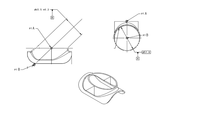
How to align this part free state?

Hello Everyone,

I've been trying for some time to align this freestate and I'm not having much luck locking it in. Could someone please point me in the right direction.

I've been trying to measure B datum as a cylinder and A Datum as an eclipse? Not used to working with parts like this. There is no C datum callout.

I greatly appreciate any tips as I've just about pulled all my hair out.
Parents
  • Do you mean the other way around? Where Datum B is an Ellipse and Datum A as a Cylinder? Picture is kind of small, I can't tell what side of the part that cylinder is on. Maybe my eyes are bad.

    Wait is datum A the side view of those curved surfaces?

  • I'm not good at roughing up things in PC-DMIS yet, so forgive me. I'm still quite a noob with this stuff.

    CIR1       =FEAT/CONTACT/CIRCLE/DEFAULT,CARTESIAN,IN,LEAST_SQR
                THEO/<-3,0,0>,<-1,0,0>,4.71,0
                ACTL/<-3,0,0>,<-1,0,0>,4.71,0
                TARG/<-3,0,0>,<-1,0,0>
                START ANG=0,END ANG=360
                ANGLE VEC=<0,0,1>
                DIRECTION=CCW
                SHOW FEATURE PARAMETERS=NO
                SHOW CONTACT PARAMETERS=NO
    CIR2       =FEAT/CONTACT/CIRCLE/DEFAULT,CARTESIAN,IN,LEAST_SQR
                THEO/<3,0,0>,<-1,0,0>,4.71,0
                ACTL/<3,0,0>,<-1,0,0>,4.71,0
                TARG/<3,0,0>,<-1,0,0>
                START ANG=0,END ANG=360
                ANGLE VEC=<0,0,1>
                DIRECTION=CCW
                SHOW FEATURE PARAMETERS=NO
                SHOW CONTACT PARAMETERS=NO
    ELL1       =FEAT/CONTACT/ELLIPSE/DEFAULT,CARTESIAN,IN
                THEO/<0,0,3>,<0,0,1>,4.71,3.2,<1,0,0>,0
                ACTL/<0,0,3>,<0,0,1>,4.71,3.2,<1,0,0>,0
                TARG/<0,0,3>,<0,0,1><1,0,0>
                START ANG=0,END ANG=0
                SHOW FEATURE PARAMETERS=NO
                SHOW CONTACT PARAMETERS=NO
    CYL1       =FEAT/CYLINDER,CARTESIAN,IN,LEAST_SQR,NO
                THEO/<-0.1,0,0>,<1,0,0>,4.71,6
                ACTL/<-0.1,0,0>,<1,0,0>,4.71,6
                CONSTR/CYLINDER,BF,CIR1,CIR2,,
    A1         =ALIGNMENT/START,RECALL:STARTUP,LIST=YES
                  ALIGNMENT/LEVEL,ZPLUS,ELL1
                  ALIGNMENT/ROTATE,XPLUS,TO,CYL1,ABOUT,ZPLUS
                  ALIGNMENT/TRANS,XAXIS,CYL1
                  ALIGNMENT/TRANS,YAXIS,CYL1
                  ALIGNMENT/TRANS,ZAXIS,ELL1
                ALIGNMENT/END

    Something like this?

    What have you tried? I know Cylinders should be able to control 4 Degrees of Freedom.

  • My understanding is that the part locates on the B datum and the rotation is locked in due to the form. A Datum levels the part out. I am trying to measure the B Datum as a cylinder but I only have a small amount of surface area to do so. Im measuring A as an eclipse. I will try what you suggested above, I appreciate your feedback.

  • I think I may have misunderstood the print, what is the "PT A" and "PT B"? I am not familiar with this type of callout. Is it similar to Datum Targets?

  • They are used to callout dimensions in the print. PT A shows the relationship between the center of the eclipse to the rest of the part and I'm assuming point a to point b is giving the angle of the B datum. I don't want to show too much information so I apologize if I'm not giving you much to work with. 

  • No, that's fine. I just wanted to make sure I was not missing any information from what you have shown already. We all got jobs to keep, no worries.

Reply Children
No Data