hexagon logo

Position of holes with no "clocking" datum

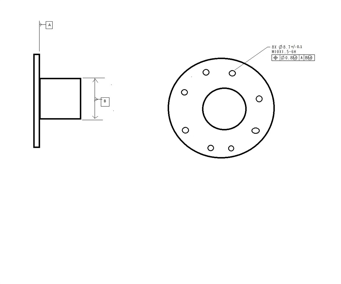
This is going to be a mouthful because I'm not even sure how to phrase what I'm trying to understand.  But here goes.  I'm struggling to understand how position works for holes that have no "clocking" datum in the FCF.  Typically I check round parts, most likely used in transmissions I think.  There is usually a face with a bolt hole pattern called out as Datum A, and a cylinder called out as Datum B, which is perpendicular to Datum A.  See by crude drawing below (I'm no artist).  In every piece of training material I've seen, anytime there is a hole or hole pattern with a position callout, the FCF always constrained all six DOF.  The majority of prints I see where I work look like my drawing.  There is nothing constraining how the holes are rotated or "clocked" around the central cylinder.  I've even seen a few prints where the holes are positioned to A only.  What I'm trying to understand is what effect this has on the results when I build the FCF to match the print.  All too often, the holes report out of position unless I add some sort of clocking feature, either by creating my own tertiary Datum from a notch or casting edge or something like that and adding it to the FCF (going against the print), or by using a legacy dimension with my current alignment in which I have all 6 DOF restrained.  I don't think I understand why they would report out of tolerance with an AB DRF.  Aren't the holes, in a sense, free to "spin" about the Datum B axis in order to find their best position?  I would think having a more restrictive DRF would make the hole positions worse, but it seems to be the opposite in my case.  Anytime I see hole positions explained in some example, the DRF always constrains all six DOF.  So I don't know if I'm dealing with bad parts, bad callouts on the print, or if I'm actually doing something wrong in my routine.  If anyone out there understands what I'm trying to understand and can explain it to me, I'd be extremely grateful.  There isn't really anyone at work who can help me.  Ultimately, I'm trying to comprehend what effects the DRF has on hole position when only 5 or fewer DOF are restrained.  

Parents
  • When you report your holes, you should be reporting them all together in the same Geometric tolerance (or XactMeasure if it is a version before 2020 R2) command so that they are treated as a pattern.  When treated as a pattern, the relationship between the holes is maintained whilst they are collectively fitted to the datums.  When you dimension the holes using legacy, you can only report one hole at a time.  This is not a problem when you have a fully constrained DRF with no material condition modifiers but in the case shown in your screenshot, it is a problem.  There is MMC on the features and MMB on the datum.  Reporting each of the holes separately would allow each one to optimize in a different direction and could easily lead to better results than if you were to report the pattern as a whole, leaving you in danger of accepting bad parts.

Reply
  • When you report your holes, you should be reporting them all together in the same Geometric tolerance (or XactMeasure if it is a version before 2020 R2) command so that they are treated as a pattern.  When treated as a pattern, the relationship between the holes is maintained whilst they are collectively fitted to the datums.  When you dimension the holes using legacy, you can only report one hole at a time.  This is not a problem when you have a fully constrained DRF with no material condition modifiers but in the case shown in your screenshot, it is a problem.  There is MMC on the features and MMB on the datum.  Reporting each of the holes separately would allow each one to optimize in a different direction and could easily lead to better results than if you were to report the pattern as a whole, leaving you in danger of accepting bad parts.

Children
  • Ok, I think that kind of explains why I was getting different results with legacy, since they were only being evaluated one at a time rather than a pattern.  But I'm not sure it explains why they were reporting better when my alignment was fully constrained vs an alignment that was only partially constrained.  For some context, I'm writing a new routine for a part whose print is from 1972.  The part is not quite the same as my drawing, but similar.  Same company too.  While the part itself is similar to my drawing, the way the Datums are defined on the print and the FCF for the hole pattern is questionable in my opinion.  That's why I was trying to use a legacy dimension, to constrain and position the hole pattern in a way that was similar to their modern prints while at the same time not making it obvious that I was going against the way this old print had it called out.  In the days before Xact Measure when everything was done with legacy, how were holes treated as a pattern if legacy only does one hole at a time?

  • In the days before Xact Measure when everything was done with legacy, how were holes treated as a pattern if legacy only does one hole at a time?

    With great difficulty!  You would probably need to treat everything as RFS (ignore the modifiers MMC and MMB), then create an alignment that levels to datum A, origins on datum B and does a 2D rotation only best-fit to all the holes.  You could then report legacy position of each of the holes.  Trying to include MMC on the holes and work out the datum shift associated with MMB on datum B would be much more complicated.