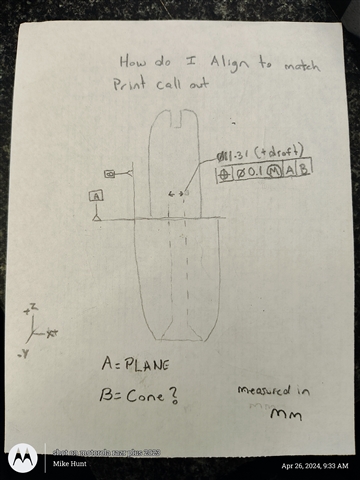
how do I make the edit window display the features I'm dimensioning and be able to edit the noms and tols from the edit window and the comments I put as well all show up on the report
Your Products have been synced, click here to refresh
Your Products have been synced, click here to refresh
how do I make the edit window display the features I'm dimensioning and be able to edit the noms and tols from the edit window and the comments I put as well all show up on the report
B.Vorhis_89 I deleted the your last comment showing the drawing. As others pointed out, you shouldn't post proprietary information unless you have express permission to do so. Ideally, try to post snippets of the drawing, redact any sensitive information or create a sketch of your own approximating the relevant information.
B.Vorhis_89 I deleted the your last comment showing the drawing. As others pointed out, you shouldn't post proprietary information unless you have express permission to do so. Ideally, try to post snippets of the drawing, redact any sensitive information or create a sketch of your own approximating the relevant information.
OK THANK YOU SIR FOR LETTING ME KNOW THAT. ITS FUNNY YOU SAID THAT BECAUSE WAS JUST WONDERING AFTER I LEFT WORK YESTERDAYIF I SHOULD HAVE CROPPED THE IMAGES WHICH ILL ATTEMPT TO DO NOW.

IF YOU NEED MOE INFO LET ME KNOW IVE GOT BASIC ITERATE AND DCC ITERATE ALIGN IVE MEASURED ALL FEATURES WITH PROPER ANGLE CHANGES NOWIM STUMPED ON THIS ALIGNMENT FOR THE FCF IS [A] YOUR LEVEL AND ROTATE, & [B] YOUR ORIGIN AND CAN YOU BRIEFLY EXPLAIN IF IM WRONG OR RIGHT HOW YOU FIGURE THIS OUT. IM SORRY IM VERY NEW TO THIS WORLD AND DIDNT KNW WHAT ALL THIS CAREER INTAILED WHEN I WAS OFFERERD THE POSITION. AT THE TIME I WAS TRYING TO GET JOB SECURITY, I KNOW I CAN GET IT WITH A LITTLE GUIDANCE IM SO GREATFUL FOR ALL THE SUPPORT
Align command:
Level Z+ to your A datum plane.
--You have no effective rotation datum (about A) defined on the print. I would use the bottom plane of the mount point for that device as my rotation datum. (or a simulated inverse IE use 1-2-3 blocks to set part on machine, with 123's sticking out and measure a plane on top of the protruding 123 block surfaces)
So Rotate to Y+ about Z axis, to that base plane.
--I would consider B datum as a circle upon intersecting the A datum plane (or relatively close). Measure B datum as a circle close to A.
Origin X&Y to B datum
Origin Z to A datum.
done :D
then, measure your inner cylinder/cone, which is a cylindrical tolerance zone that's perpendicular to A, and centered about B.
| © 2024 Hexagon AB and/or its subsidiaries. | Privacy Policy | Cloud Services Agreement |