hexagon logo

Diametric clearance and GD&T default measurements

Hello PC-DMIS forum, 

I have a question regarding Diametric clearance and how  measuring a diameter with GD&T DEFUALT changes the measurement.

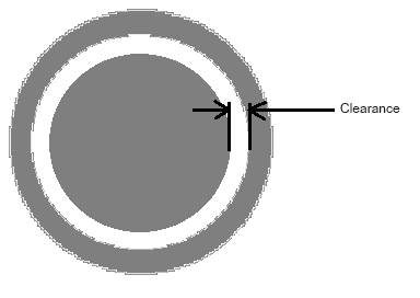
we are machining 2 pieces for a welded ring the inner ring must fit into the outer ring. the tolerance for the outer is 10.320-10.316 (inches) and the inner diameter is 10.615-10.610 with a note stating the diametric clearance between the two should be .0005 to .0025

I am calculating the diameter using the normal dimensioning tool and outputting the data through DEFULT on a GD&T callout. the GD&T callout makes the inner rings O.D. bigger while making the I.D. smaller and making the diametric clearance look better.

my question is, is using the DEFUALT tolerancing for the diameter more right to achieve the callout the print is asking for?

 I have never dealt with diametric clearances on any other part so any advice would be helpful. Thank you,

Parents
  • When the Geometric Tolerance command's math settings are set to DEFAULT, it means that they are using the default calculation method as defined by whichever standard you are referencing (ISO 1101 or ASME Y14.5).  You don't mention which standard you are working to but I will assume it's ASME.

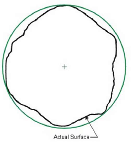
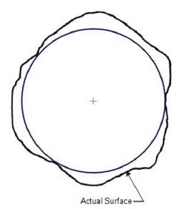
    Under ASME, when evaluating size with DEFAULT math, we give two values - the UAME (Unrelated Actual Mating Envelope) and the local size (which can be opposed points or circular elements).  The UAME is essentially the mating envelope, external to material - think of this as the smallest ring gauge that would physically fit over a boss or the largest plug gauge that would physically fit into a hole.

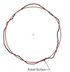
    When looking at the diameter values of the features in the edit window, they are based on the fitting algorithm selected for the feature measurement - usually Least Squares.  A least squares calculation is an average of all the measurement points and as such, will always yield a circle that is inside the physical surface.

    Least Squares

    External Circle UAME

    Internal Circle UAME

    If I understand correctly, you have an outer ring which has an inner diameter and an inner ring which has an outer diameter.

    If that is the case then I'd expect the amount of clearance to be smaller when using the Geometric Tolerance DEFAULT math than when using legacy dimensioning.

Reply
  • When the Geometric Tolerance command's math settings are set to DEFAULT, it means that they are using the default calculation method as defined by whichever standard you are referencing (ISO 1101 or ASME Y14.5).  You don't mention which standard you are working to but I will assume it's ASME.

    Under ASME, when evaluating size with DEFAULT math, we give two values - the UAME (Unrelated Actual Mating Envelope) and the local size (which can be opposed points or circular elements).  The UAME is essentially the mating envelope, external to material - think of this as the smallest ring gauge that would physically fit over a boss or the largest plug gauge that would physically fit into a hole.

    When looking at the diameter values of the features in the edit window, they are based on the fitting algorithm selected for the feature measurement - usually Least Squares.  A least squares calculation is an average of all the measurement points and as such, will always yield a circle that is inside the physical surface.

    Least Squares

    External Circle UAME

    Internal Circle UAME

    If I understand correctly, you have an outer ring which has an inner diameter and an inner ring which has an outer diameter.

    If that is the case then I'd expect the amount of clearance to be smaller when using the Geometric Tolerance DEFAULT math than when using legacy dimensioning.

Children