hexagon logo

Best fit alignment for troubleshooting manufacturing processes?

Can someone explain how a best fit alignments used to troubleshoot manufacturing processes?

Pros/ cons of best fit vs normal alignment?

I'm having a hard time understanding how using a best fit would help with troubleshooting over a normal alignment. 

Please provide detail in explanations.

Thanks. 

Parents
  • If you are using best-fit alignments to troubleshoot your process, getting to the end result of that troubleshooting will take a looooong time compared to using a "regular" alignment.

    Scenario:
    Bolthole pattern with one (1) hole as outlier (out of tolerance).

    Using a best-fit alignment using all the holes will look for the alignment with the smallest sum of all errors.This means that the alignment will disperse the total deviation (for that one single hole) over the entire set of holes. All the holes that wasn't causing any concern has now gotten a share of the deviation from that one outlier (one deviating hole). Giving this report to a machinist will make that machinist adjust *all* the holes instead of that one (1) hole. Rinse and repeat...

    Using a "regular" geometric/prismatic alignment, possibly following the drawing or the machining setup would probably tell you that this one (1) hole is out of spec. Giving that report to the machinist will (hopefully) make him/her change the settings for that one hole and not touching the in-spec ones.

    Even if the drawing would say that it is OK to use a best-fit alignment, if you are on the manufacturing side of the part, you should not use best-fit during manufacturing - only for final inspection (checking it per the drawing). During the manufacturing/machining process you should use the same alignment as the manufacturing setup (the machining setup) uses, in order to be able to be useful for those people. If you manage to make a part that is within tolerance using the machining setup it will most likely pass through the final verification where the drawing allows for best-fit.

  • This explanation makes sense for the type of information a normal alignment shows us when measuring parts but what would be the benefit of using a best fit? Training said to use best fits to troubleshoot manufacturing processes but doesn't explain exactly how. Maybe the point is that it rules out variation in the datums? I can look back in my slides and see where it says that, but my engineer has been asking if I can do "best fits" and I'm not sure exactly what they are trying to test by asking me to use it.

  • he is trying to get you to pass a part that isn't in tolerance to the datums.

  • I don't get that impression from him. I think he is really trying to get me to figure out how to use it as a tool. We do production as well as R&D. Maybe the better question is, "what is the point of best fits?" I mean if all we ever needed was a normal alignment then why even offer the best fits in PC-Dmis? I feel like we're missing something here.  

  • Well, if you include the datums together with the other toleranced features the total deviation of all of them will be spread across the features in the best fit alignment. So, if your datums were correct, they now get a slice of that deviation caused by other features. 

    There are several use cases for best fit, but as I said earlier, if I was in manufacturing I would never use that for parts going out to customers, instead I'd choose the "tougher " way by using the machining datums and evaluate through that setup. After that has been cleared and passed, I'd do a check final according to the drawing (that allows for best fit) and ship that protocol along with the parts. This final protocol (using best fit) should show better results than with the machining setup evaluations.

  • if he doesn't know how to use it, then he is looking for work-arounds, how does he even know about it?  The only uses I have ever found for best-fit are:

    (1) NO datums on a 3D free-form part to balance the entire part, every feature checked and used.

    (2) Getting the bottom segment of a TP to report the relationship of the holes without the use of GeoTol or the other thing that have/had.

    I'm not saying those are the only uses, but in 30-some years, those are the only uses I have used it for.

  • (1.5) Doesn't even need to be a free-form part (but that immediately springs to mind), but "Every feature checked and used." is the important thing here.

  • and with something on the print like "entire part ~ profile/surf of X.XX"

  • It depends on the situation.

    For example, we'd use a best fit alignment when assessing either positions or profile (using Legacy dimensions) when the datum system (Datum Reference Frame) doesn't constrain all 6DOF.

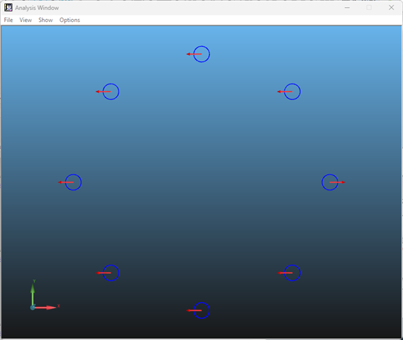
    To assess pass/fail we'd typically use a Min/Max solution, however (to use VPT's example above) if we were checking a hole pattern, and had one hole that was incorrect, that one hole would show out, but also make the others show out (and at least one of them by an equal amount).

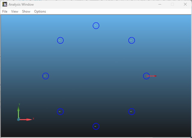
    If we changed the best fit type to least square, then although the one bad hole would 'pull' on the others a bit, it would be obvious which was the hole with the problem.

    Min/Max best fit on a hole pattern shows all holes being out -  the Out of Tol values would be the same for all holes, so without the graphic it might make you think there was some underlying issue.

    If we change the best fit type to least square we can see that although the other 7 holes have inherited some of the error from the poor hole, it's obvious which hole is impacting the results.

  • Best-fit alignments have many uses, it all depends on what you're trying to accomplish.  Profile, for example, employs a vector min/max best-fit during the optimisation - same for form tolerances (flatness, circularity, cylindricity, straightness).  Pointcloud/mesh alignments essentially best-fit the gathered data to the CAD nominals.  Material conditions (MMC/LMC/MMB/LMB) allow a certain amount of best-fitting whilst maintaining any applicable constraints.  Etc,

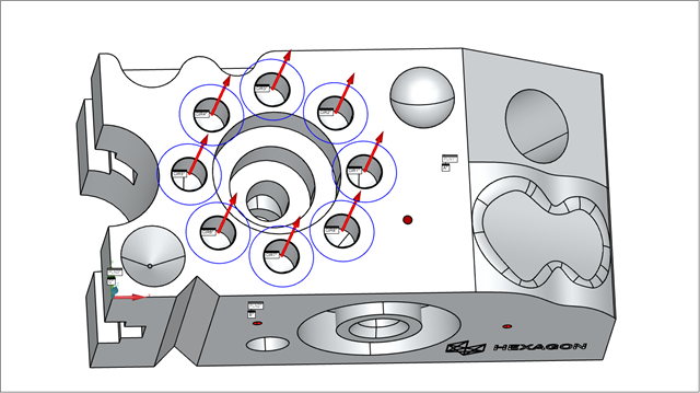
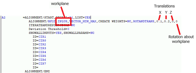
    When it comes to trouble-shooting for production, best-fit alignments can be useful to determine whether a single adjustment can be applied to correct a group of features or even the entire part.  For example, suppose you had a pattern of holes who's relationship to each other was good, but the entire pattern was off location with respect to the datums.  If you created a traditional alignment to those datums (matching the DRF on the drawing) and then performed a 2D best-fit of all the holes, you could use the best-fit alignment's offset values to determine how much you need to move things - either by machining more or less material from one or more datum surface(s) or by adjusting the machine's work offsets for the operation that produces the hole pattern.  This is shown in a very simplistic way in my example below.  I created a routine where I'd shifted the datum B datum surface by 0.2 and the datum C surface by 0.1.  The hole pattern is perfect to the nominal CAD data but, because the datums have too much material on them, the holes report out of position.

    PLN1       =FEAT/CONTACT/PLANE/DEFAULT,CARTESIAN,NONE,LEAST_SQR
                THEO/<157.968,67.59,0>,<0,0,1>
                ACTL/<157.968,67.59,0>,<0,0,1>
                TARG/<157.968,67.59,0>,<0,0,1>
                ANGLE VEC=<1,0,0>,SQUARE
                SHOW FEATURE PARAMETERS=NO
                SHOW CONTACT PARAMETERS=NO
    PLN2       =FEAT/CONTACT/PLANE/DEFAULT,CARTESIAN,NONE,LEAST_SQR
                THEO/<64.465,0,-8.745>,<0,-1,0>
                ACTL/<64.465,-0.2,-8.745>,<0,-1,0>
                TARG/<64.465,0,-8.745>,<0,-1,0>
                ANGLE VEC=<1,0,0>,SQUARE
                SHOW FEATURE PARAMETERS=NO
                SHOW CONTACT PARAMETERS=NO
    PLN3       =FEAT/CONTACT/PLANE/DEFAULT,CARTESIAN,NONE,LEAST_SQR
                THEO/<0,18.792,-13.095>,<-1,0,0>
                ACTL/<-0.1,18.792,-13.095>,<-1,0,0>
                TARG/<0,18.792,-13.095>,<-1,0,0>
                ANGLE VEC=<0,0,1>,SQUARE
                SHOW FEATURE PARAMETERS=NO
                SHOW CONTACT PARAMETERS=NO
    A1         =ALIGNMENT/START,RECALL:STARTUP,LIST=YES
                  ALIGNMENT/LEVEL,ZPLUS,PLN1
                  ALIGNMENT/TRANS,ZAXIS,PLN1
                  ALIGNMENT/ROTATE,YMINUS,TO,PLN2,ABOUT,ZPLUS
                  ALIGNMENT/TRANS,YAXIS,PLN2
                  ALIGNMENT/TRANS,XAXIS,PLN3
                ALIGNMENT/END
    CIR1       =FEAT/CONTACT/CIRCLE/DEFAULT,CARTESIAN,IN,LEAST_SQR
                THEO/<121,60,0>,<0,0,1>,16.4
                ACTL/<121.1,60.2,0>,<0,0,1>,16.4
                TARG/<121,60,0>,<0,0,1>
                START ANG=0,END ANG=360
                ANGLE VEC=<1,0,0>
                DIRECTION=CCW
                SHOW FEATURE PARAMETERS=NO
                SHOW CONTACT PARAMETERS=NO
    CIR2       =FEAT/CONTACT/CIRCLE/DEFAULT,CARTESIAN,IN,LEAST_SQR
                THEO/<108.991,88.991,0>,<0,0,1>,16.4
                ACTL/<109.091,89.191,0>,<0,0,1>,16.4
                TARG/<108.991,88.991,0>,<0,0,1>
                START ANG=0,END ANG=360
                ANGLE VEC=<1,0,0>
                DIRECTION=CCW
                SHOW FEATURE PARAMETERS=NO
                SHOW CONTACT PARAMETERS=NO
    CIR3       =FEAT/CONTACT/CIRCLE/DEFAULT,CARTESIAN,IN,LEAST_SQR
                THEO/<80,101,0>,<0,0,1>,16.4
                ACTL/<80.1,101.2,0>,<0,0,1>,16.4
                TARG/<80,101,0>,<0,0,1>
                START ANG=0,END ANG=360
                ANGLE VEC=<1,0,0>
                DIRECTION=CCW
                SHOW FEATURE PARAMETERS=NO
                SHOW CONTACT PARAMETERS=NO
    CIR4       =FEAT/CONTACT/CIRCLE/DEFAULT,CARTESIAN,IN,LEAST_SQR
                THEO/<51.009,88.991,0>,<0,0,1>,16.4
                ACTL/<51.109,89.191,0>,<0,0,1>,16.4
                TARG/<51.009,88.991,0>,<0,0,1>
                START ANG=0,END ANG=360
                ANGLE VEC=<1,0,0>
                DIRECTION=CCW
                SHOW FEATURE PARAMETERS=NO
                SHOW CONTACT PARAMETERS=NO
    CIR5       =FEAT/CONTACT/CIRCLE/DEFAULT,CARTESIAN,IN,LEAST_SQR
                THEO/<39,60,0>,<0,0,1>,16.4
                ACTL/<39.1,60.2,0>,<0,0,1>,16.4
                TARG/<39,60,0>,<0,0,1>
                START ANG=0,END ANG=360
                ANGLE VEC=<1,0,0>
                DIRECTION=CCW
                SHOW FEATURE PARAMETERS=NO
                SHOW CONTACT PARAMETERS=NO
    CIR6       =FEAT/CONTACT/CIRCLE/DEFAULT,CARTESIAN,IN,LEAST_SQR
                THEO/<51.009,31.009,0>,<0,0,1>,16.4
                ACTL/<51.109,31.209,0>,<0,0,1>,16.4
                TARG/<51.009,31.009,0>,<0,0,1>
                START ANG=0,END ANG=360
                ANGLE VEC=<1,0,0>
                DIRECTION=CCW
                SHOW FEATURE PARAMETERS=NO
                SHOW CONTACT PARAMETERS=NO
    CIR7       =FEAT/CONTACT/CIRCLE/DEFAULT,CARTESIAN,IN,LEAST_SQR
                THEO/<80,19,0>,<0,0,1>,16.4
                ACTL/<80.1,19.2,0>,<0,0,1>,16.4
                TARG/<80,19,0>,<0,0,1>
                START ANG=0,END ANG=360
                ANGLE VEC=<1,0,0>
                DIRECTION=CCW
                SHOW FEATURE PARAMETERS=NO
                SHOW CONTACT PARAMETERS=NO
    CIR8       =FEAT/CONTACT/CIRCLE/DEFAULT,CARTESIAN,IN,LEAST_SQR
                THEO/<108.991,31.009,0>,<0,0,1>,16.4
                ACTL/<109.091,31.209,0>,<0,0,1>,16.4
                TARG/<108.991,31.009,0>,<0,0,1>
                START ANG=0,END ANG=360
                ANGLE VEC=<1,0,0>
                DIRECTION=CCW
                SHOW FEATURE PARAMETERS=NO
                SHOW CONTACT PARAMETERS=NO
    A2         =ALIGNMENT/START,RECALL:A1,LIST=YES
                  ALIGNMENT/BF2D,ZPLUS,VECTOR_MIN_MAX,CREATE WEIGHTS=NO,ROTANDTRANS,0.1,0.2,0,0
                  ITERATEANDREPIERCECAD=NO
                  Deviation Threshold=0
                  SHOWALLINPUTS=NO,SHOWALLPARAMS=NO
                ALIGNMENT/END
                DATDEF/A,FEATURES=PLN1,,
                DATDEF/B,FEATURES=PLN2,,
                DATDEF/C,FEATURES=PLN3,,
    FCFLOC1    =GEOMETRIC_TOLERANCE/STANDARD=ASME Y14.5,SHOWEXPANDED=YES,
                DESCRIPTION=OFF,,
                FEATURE_MATH=DEFAULT,DATUM_MATH=DEFAULT,DISPLAY_COORDS=DRF,
                UNITS=MM,OUTPUT=BOTH,ARROWDENSITY=100,
                SIZE/NOMINAL=16.4,UPPER TOLERANCE=0.25,LOWER TOLERANCE=0.25,
                REPORT_LOCAL_SIZE=ON,LOCAL_SIZE_METHOD=OPPOSED_POINTS,
                  CIR1:
                    UAME SIZE:16.400,
                    LOCAL SIZE:16.400,
                  CIR2:
                    UAME SIZE:16.400,
                    LOCAL SIZE:16.400,
                  CIR3:
                    UAME SIZE:16.400,
                    LOCAL SIZE:16.400,
                  CIR4:
                    UAME SIZE:16.400,
                    LOCAL SIZE:16.400,
                  CIR5:
                    UAME SIZE:16.400,
                    LOCAL SIZE:16.400,
                  CIR6:
                    UAME SIZE:16.400,
                    LOCAL SIZE:16.400,
                  CIR7:
                    UAME SIZE:16.400,
                    LOCAL SIZE:16.400,
                  CIR8:
                    UAME SIZE:16.400,
                    LOCAL SIZE:16.400,
                SEGMENT_1,POSITION,DIAMETER,0.3,__,__,A,B,__,C,__,
                TEXT=OFF,CADGRAPH=OFF,REPORTGRAPH=OFF,MULT=100,
                  MEASURED:
                    CIR1:0.447,
                    CIR2:0.447,
                    CIR3:0.447,
                    CIR4:0.447,
                    CIR5:0.447,
                    CIR6:0.447,
                    CIR7:0.447,
                    CIR8:0.447,
                ADD
                FEATURES/CIR1,CIR2,CIR3,CIR4,CIR5,CIR6,CIR7,CIR8,,

    Turning CAD graphical analysis on in the position command, allows you to visualise the error...

    It does not, however, tell the machinist how much adjustment to apply, it only shows the direction in which the holes are out.  If you combine this visual information with the numbers from the best-fit alignment, you have the full picture...

Reply
  • Best-fit alignments have many uses, it all depends on what you're trying to accomplish.  Profile, for example, employs a vector min/max best-fit during the optimisation - same for form tolerances (flatness, circularity, cylindricity, straightness).  Pointcloud/mesh alignments essentially best-fit the gathered data to the CAD nominals.  Material conditions (MMC/LMC/MMB/LMB) allow a certain amount of best-fitting whilst maintaining any applicable constraints.  Etc,

    When it comes to trouble-shooting for production, best-fit alignments can be useful to determine whether a single adjustment can be applied to correct a group of features or even the entire part.  For example, suppose you had a pattern of holes who's relationship to each other was good, but the entire pattern was off location with respect to the datums.  If you created a traditional alignment to those datums (matching the DRF on the drawing) and then performed a 2D best-fit of all the holes, you could use the best-fit alignment's offset values to determine how much you need to move things - either by machining more or less material from one or more datum surface(s) or by adjusting the machine's work offsets for the operation that produces the hole pattern.  This is shown in a very simplistic way in my example below.  I created a routine where I'd shifted the datum B datum surface by 0.2 and the datum C surface by 0.1.  The hole pattern is perfect to the nominal CAD data but, because the datums have too much material on them, the holes report out of position.

    PLN1       =FEAT/CONTACT/PLANE/DEFAULT,CARTESIAN,NONE,LEAST_SQR
                THEO/<157.968,67.59,0>,<0,0,1>
                ACTL/<157.968,67.59,0>,<0,0,1>
                TARG/<157.968,67.59,0>,<0,0,1>
                ANGLE VEC=<1,0,0>,SQUARE
                SHOW FEATURE PARAMETERS=NO
                SHOW CONTACT PARAMETERS=NO
    PLN2       =FEAT/CONTACT/PLANE/DEFAULT,CARTESIAN,NONE,LEAST_SQR
                THEO/<64.465,0,-8.745>,<0,-1,0>
                ACTL/<64.465,-0.2,-8.745>,<0,-1,0>
                TARG/<64.465,0,-8.745>,<0,-1,0>
                ANGLE VEC=<1,0,0>,SQUARE
                SHOW FEATURE PARAMETERS=NO
                SHOW CONTACT PARAMETERS=NO
    PLN3       =FEAT/CONTACT/PLANE/DEFAULT,CARTESIAN,NONE,LEAST_SQR
                THEO/<0,18.792,-13.095>,<-1,0,0>
                ACTL/<-0.1,18.792,-13.095>,<-1,0,0>
                TARG/<0,18.792,-13.095>,<-1,0,0>
                ANGLE VEC=<0,0,1>,SQUARE
                SHOW FEATURE PARAMETERS=NO
                SHOW CONTACT PARAMETERS=NO
    A1         =ALIGNMENT/START,RECALL:STARTUP,LIST=YES
                  ALIGNMENT/LEVEL,ZPLUS,PLN1
                  ALIGNMENT/TRANS,ZAXIS,PLN1
                  ALIGNMENT/ROTATE,YMINUS,TO,PLN2,ABOUT,ZPLUS
                  ALIGNMENT/TRANS,YAXIS,PLN2
                  ALIGNMENT/TRANS,XAXIS,PLN3
                ALIGNMENT/END
    CIR1       =FEAT/CONTACT/CIRCLE/DEFAULT,CARTESIAN,IN,LEAST_SQR
                THEO/<121,60,0>,<0,0,1>,16.4
                ACTL/<121.1,60.2,0>,<0,0,1>,16.4
                TARG/<121,60,0>,<0,0,1>
                START ANG=0,END ANG=360
                ANGLE VEC=<1,0,0>
                DIRECTION=CCW
                SHOW FEATURE PARAMETERS=NO
                SHOW CONTACT PARAMETERS=NO
    CIR2       =FEAT/CONTACT/CIRCLE/DEFAULT,CARTESIAN,IN,LEAST_SQR
                THEO/<108.991,88.991,0>,<0,0,1>,16.4
                ACTL/<109.091,89.191,0>,<0,0,1>,16.4
                TARG/<108.991,88.991,0>,<0,0,1>
                START ANG=0,END ANG=360
                ANGLE VEC=<1,0,0>
                DIRECTION=CCW
                SHOW FEATURE PARAMETERS=NO
                SHOW CONTACT PARAMETERS=NO
    CIR3       =FEAT/CONTACT/CIRCLE/DEFAULT,CARTESIAN,IN,LEAST_SQR
                THEO/<80,101,0>,<0,0,1>,16.4
                ACTL/<80.1,101.2,0>,<0,0,1>,16.4
                TARG/<80,101,0>,<0,0,1>
                START ANG=0,END ANG=360
                ANGLE VEC=<1,0,0>
                DIRECTION=CCW
                SHOW FEATURE PARAMETERS=NO
                SHOW CONTACT PARAMETERS=NO
    CIR4       =FEAT/CONTACT/CIRCLE/DEFAULT,CARTESIAN,IN,LEAST_SQR
                THEO/<51.009,88.991,0>,<0,0,1>,16.4
                ACTL/<51.109,89.191,0>,<0,0,1>,16.4
                TARG/<51.009,88.991,0>,<0,0,1>
                START ANG=0,END ANG=360
                ANGLE VEC=<1,0,0>
                DIRECTION=CCW
                SHOW FEATURE PARAMETERS=NO
                SHOW CONTACT PARAMETERS=NO
    CIR5       =FEAT/CONTACT/CIRCLE/DEFAULT,CARTESIAN,IN,LEAST_SQR
                THEO/<39,60,0>,<0,0,1>,16.4
                ACTL/<39.1,60.2,0>,<0,0,1>,16.4
                TARG/<39,60,0>,<0,0,1>
                START ANG=0,END ANG=360
                ANGLE VEC=<1,0,0>
                DIRECTION=CCW
                SHOW FEATURE PARAMETERS=NO
                SHOW CONTACT PARAMETERS=NO
    CIR6       =FEAT/CONTACT/CIRCLE/DEFAULT,CARTESIAN,IN,LEAST_SQR
                THEO/<51.009,31.009,0>,<0,0,1>,16.4
                ACTL/<51.109,31.209,0>,<0,0,1>,16.4
                TARG/<51.009,31.009,0>,<0,0,1>
                START ANG=0,END ANG=360
                ANGLE VEC=<1,0,0>
                DIRECTION=CCW
                SHOW FEATURE PARAMETERS=NO
                SHOW CONTACT PARAMETERS=NO
    CIR7       =FEAT/CONTACT/CIRCLE/DEFAULT,CARTESIAN,IN,LEAST_SQR
                THEO/<80,19,0>,<0,0,1>,16.4
                ACTL/<80.1,19.2,0>,<0,0,1>,16.4
                TARG/<80,19,0>,<0,0,1>
                START ANG=0,END ANG=360
                ANGLE VEC=<1,0,0>
                DIRECTION=CCW
                SHOW FEATURE PARAMETERS=NO
                SHOW CONTACT PARAMETERS=NO
    CIR8       =FEAT/CONTACT/CIRCLE/DEFAULT,CARTESIAN,IN,LEAST_SQR
                THEO/<108.991,31.009,0>,<0,0,1>,16.4
                ACTL/<109.091,31.209,0>,<0,0,1>,16.4
                TARG/<108.991,31.009,0>,<0,0,1>
                START ANG=0,END ANG=360
                ANGLE VEC=<1,0,0>
                DIRECTION=CCW
                SHOW FEATURE PARAMETERS=NO
                SHOW CONTACT PARAMETERS=NO
    A2         =ALIGNMENT/START,RECALL:A1,LIST=YES
                  ALIGNMENT/BF2D,ZPLUS,VECTOR_MIN_MAX,CREATE WEIGHTS=NO,ROTANDTRANS,0.1,0.2,0,0
                  ITERATEANDREPIERCECAD=NO
                  Deviation Threshold=0
                  SHOWALLINPUTS=NO,SHOWALLPARAMS=NO
                ALIGNMENT/END
                DATDEF/A,FEATURES=PLN1,,
                DATDEF/B,FEATURES=PLN2,,
                DATDEF/C,FEATURES=PLN3,,
    FCFLOC1    =GEOMETRIC_TOLERANCE/STANDARD=ASME Y14.5,SHOWEXPANDED=YES,
                DESCRIPTION=OFF,,
                FEATURE_MATH=DEFAULT,DATUM_MATH=DEFAULT,DISPLAY_COORDS=DRF,
                UNITS=MM,OUTPUT=BOTH,ARROWDENSITY=100,
                SIZE/NOMINAL=16.4,UPPER TOLERANCE=0.25,LOWER TOLERANCE=0.25,
                REPORT_LOCAL_SIZE=ON,LOCAL_SIZE_METHOD=OPPOSED_POINTS,
                  CIR1:
                    UAME SIZE:16.400,
                    LOCAL SIZE:16.400,
                  CIR2:
                    UAME SIZE:16.400,
                    LOCAL SIZE:16.400,
                  CIR3:
                    UAME SIZE:16.400,
                    LOCAL SIZE:16.400,
                  CIR4:
                    UAME SIZE:16.400,
                    LOCAL SIZE:16.400,
                  CIR5:
                    UAME SIZE:16.400,
                    LOCAL SIZE:16.400,
                  CIR6:
                    UAME SIZE:16.400,
                    LOCAL SIZE:16.400,
                  CIR7:
                    UAME SIZE:16.400,
                    LOCAL SIZE:16.400,
                  CIR8:
                    UAME SIZE:16.400,
                    LOCAL SIZE:16.400,
                SEGMENT_1,POSITION,DIAMETER,0.3,__,__,A,B,__,C,__,
                TEXT=OFF,CADGRAPH=OFF,REPORTGRAPH=OFF,MULT=100,
                  MEASURED:
                    CIR1:0.447,
                    CIR2:0.447,
                    CIR3:0.447,
                    CIR4:0.447,
                    CIR5:0.447,
                    CIR6:0.447,
                    CIR7:0.447,
                    CIR8:0.447,
                ADD
                FEATURES/CIR1,CIR2,CIR3,CIR4,CIR5,CIR6,CIR7,CIR8,,

    Turning CAD graphical analysis on in the position command, allows you to visualise the error...

    It does not, however, tell the machinist how much adjustment to apply, it only shows the direction in which the holes are out.  If you combine this visual information with the numbers from the best-fit alignment, you have the full picture...

Children