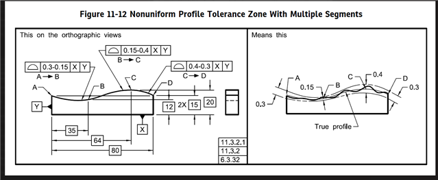
PC-DMIS does not currently support nonuniform profile tolerance zones. Measure each segment individually and apply a simultaneous evaluation (if applicable).
When your Datum Reference Frame (DRF) doesn't fully constrain all 6 Degrees of Freedom (DoF) you can have datum shift (or datum feature displacement). As an example, imagine a primary datum plane and a secondary datum cylinder perpendicular to primary. The DRF does not constrain rotation about the primary datum normal vector, so that freedom in rotation can be taken advantage of. Imagine a second cylinder perpendicular to primary. If it were positioned back to primary and secondary, the DRF will rotate in such a way that will minimize the actual value. If you have a third cylinder positioned the same way (same DRF), they must be evaluated simultaneously (i.e. the rotation that is performed to minimize an actual value cannot be different for different features as that would not represent true function).
In essence, all position and profile tolerances utilizing the same DRF need to be evaluated simultaneously. Refer to ASME Y14.5-2018 Para. 7.19.