hexagon logo

Workpiece Offset Machine Coordinate vs Manual Alignment

Hey all, 

We've got some bright Machinists here that are tired of having the CMM programmer manual align their parts every few months. We get a few repeat jobs once every 6 months or so, and by that time either probe calibration, machine settling or by some other factor I'm not aware of our programs will need a new manual alignment. Afterwards, we unmark these features and let the job run in DCC mode. (sidenote, my hunch is that the manual alignment feature's measured coordinates are married to the previous probe alignment, so after a new alignment they don't 'match' the expected coordinates for DCC mode)


Anyways here is my question/discussion; What are the pros/cons of using a manual alignment vs a know x,y,z position for part programs?
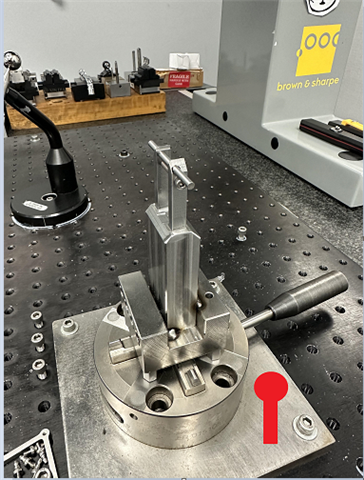
I don't have a good answer for rebuttal to our machinists, and I'm starting to wonder if some of our programs would be better off with hard-coded workpiece offsets. We use an Erowa chuck with custom fixturing for 70% of our jobs, so these parts are highly repeatable. 

What are your thoughts?

Parents
  • Thinking you need to smack your programmer with a rolled-up newspaper... 

    But alas, have them look into read point alignments. They will make it much nicer for your machinists to come in and look at a picture of which direction to load the part, move the probe into the appropriate hole or corner of the part and hit go. 

  • I'm one of two main programmers, I'll give myself a bonk for not knowing this.. 

    Have you had good luck with read point alignments? We currently run the manual align, then a DCC align, and a final "to-Datum" alignment. I'm wondering how many iterative alignments are needed to weed out the errors. Also, if the CAD origin of the part is floating in space, would i need to transform/move the origin before attempting a read point alignment?

Reply
  • I'm one of two main programmers, I'll give myself a bonk for not knowing this.. 

    Have you had good luck with read point alignments? We currently run the manual align, then a DCC align, and a final "to-Datum" alignment. I'm wondering how many iterative alignments are needed to weed out the errors. Also, if the CAD origin of the part is floating in space, would i need to transform/move the origin before attempting a read point alignment?

Children
  • Don't bop yourself too hard! 

    99% of all programs at my last job were readpoint alignments. As long as you provide an image (later we just used a CAD model of the tooling, on the tooling plate in the correct location, holding the part) it was about 95% successful unless you had a particularly inept shop monkey.

    In your case it looks like you have fixtures for your parts which is even better. You could just cheat and add a tooling ball to your subplate with a readpoint above the tooling ball. Then the machine can locate the ball, then move to the part and perform a rough align, then a datum alignment, if you're feeling spicy add a second datum alignment.

    For a readpoint alignment you need to know the distance from your readpoint to the trihedron for it to work, if its floating in space and not touching the part that can make it harder. 

  • Once I mastered read point alignments I never looked back. I pull up older programs I wrote and if it's a manual alignment I change it. Only new tooling inspection I manual align because I might never see it again and it's not worth the time.