hexagon logo

Workpiece Offset Machine Coordinate vs Manual Alignment

Hey all, 

We've got some bright Machinists here that are tired of having the CMM programmer manual align their parts every few months. We get a few repeat jobs once every 6 months or so, and by that time either probe calibration, machine settling or by some other factor I'm not aware of our programs will need a new manual alignment. Afterwards, we unmark these features and let the job run in DCC mode. (sidenote, my hunch is that the manual alignment feature's measured coordinates are married to the previous probe alignment, so after a new alignment they don't 'match' the expected coordinates for DCC mode)


Anyways here is my question/discussion; What are the pros/cons of using a manual alignment vs a know x,y,z position for part programs?
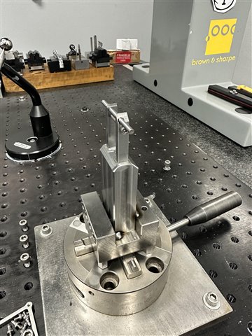
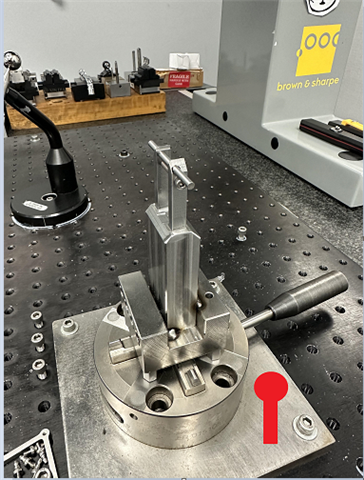
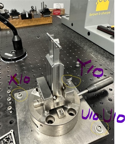
I don't have a good answer for rebuttal to our machinists, and I'm starting to wonder if some of our programs would be better off with hard-coded workpiece offsets. We use an Erowa chuck with custom fixturing for 70% of our jobs, so these parts are highly repeatable. 

What are your thoughts?

  • Thinking you need to smack your programmer with a rolled-up newspaper... 

    But alas, have them look into read point alignments. They will make it much nicer for your machinists to come in and look at a picture of which direction to load the part, move the probe into the appropriate hole or corner of the part and hit go. 

  • I second the read point suggestion. I know people love manual alignments, and I don't dislike them. But we have operators on off shifts who would not follow manual alignment instructions too well. It's bad enough when they can't position the readpoint correctly, or don't put the fixturing in the correct X, Y and wonder why their part will not run, or it's crooked.

  • If you're using an Erowa chuck that is permanently bolted to the CMM bed and never moves, then it might be better to have a program that aligns that chuck and saves an external alignment.  Then, instead of having a manual alignment that gets unmarked in each of your programs, you would just recall the external fixture alignment.  That way, whenever the fixture position needs updating, you just run the fixture alignment program and it's position is updated for all programs, negating the need to redo the manual alignment in every program you need to run.

  • probe calibrations (if done correctly) should not ever effect an alignment, but HOMING the machine will.  HOME is not 'carved in stone', HOME is triggered by the machine passing a mechanical 'thing' on the machine and thus setting XYZ zero.  Since this is never perfect, the XYZ values will slowly drift over time.

  • I'm one of two main programmers, I'll give myself a bonk for not knowing this.. 

    Have you had good luck with read point alignments? We currently run the manual align, then a DCC align, and a final "to-Datum" alignment. I'm wondering how many iterative alignments are needed to weed out the errors. Also, if the CAD origin of the part is floating in space, would i need to transform/move the origin before attempting a read point alignment?

  • I was thinking of this, but our custom fixturing vary in height and holding location for the parts, despite being welded to erowa blocks. So then I would need some xyz offset from the erowa alignment to keep everything in agreement. Correct? Here is an image of one of the fixtures. We have 3 part styles for this job, 3 corresponding fixtures which have different heights. We have give or take 15 different vices and fixturings to choose from for all our jobs...lots of small, complicated parts. 

  • Don't bop yourself too hard! 

    99% of all programs at my last job were readpoint alignments. As long as you provide an image (later we just used a CAD model of the tooling, on the tooling plate in the correct location, holding the part) it was about 95% successful unless you had a particularly inept shop monkey.

    In your case it looks like you have fixtures for your parts which is even better. You could just cheat and add a tooling ball to your subplate with a readpoint above the tooling ball. Then the machine can locate the ball, then move to the part and perform a rough align, then a datum alignment, if you're feeling spicy add a second datum alignment.

    For a readpoint alignment you need to know the distance from your readpoint to the trihedron for it to work, if its floating in space and not touching the part that can make it harder. 

  • I don't do readpoint or manual alignments anymore. I simply recall an external plate alignment and go right into the DCC alignment. I created a threaded plate and the standoffs along with other tooling I use from Solidworks (not a fan of quick fixture) and all that needs to happen is the operator needs to place the fixture in the place per the display with the correct size standoffs. 95% are the same size. All programs now start and end in the tool changer "safe zone". The ones that are more detailed I have a set-up program with comments to tell the operator what size standoff to use and the CMM steps through each location. If your Erowa chuck can be placed in the same spot to measure all parts it might be an easier way. 

    If I have a part that I can't lock in place the same every time, I still recall the plate alignment and then do a readpoint alignment. That only happens when my last translation can't be fixtured on the plate.

    It takes time to transform the part and each detail the first time but after that it's as easy as looking at the display and comment/pic.

  • I prefer both readpoint and external alignment. Based on the picture you provided, I plan to add slot locations with pictures and notes (e.g., X10 Y10 U10 with M8 bolts) to improve fixture location accuracy. This will help operators follow the setup more effectively.

    For readpoint alignment, it works better with progress alignment, offering improved efficiency and convergence.

  • Hello all, 

    I have to say I learned more than I bargained for with this one!  Very interesting stuff...

    I'm investigating read point alignments now and incorporating them into some programs. The machinists are unwilling to move the CMM with the jogbox and enjoy the ability to put a part into the fixture, hit go and walk away. Now I know i can use a read point alignment to save myself or the other programmer some time instead of using manual pickups by using the readpoint for the initial alignment and then marking the feature so it doesn't execute on production run. It's a better replacement for manual alignments, which leave more room for error IMO. 

    I love the idea of using a known sphere/slot/position on our Erowa fixture for the readpoint. My only concern is nailing the xyz origin offset for each fixture/part/program and communicating that new method of programming with the rest of our team here. It's a daunting task. On top of that, I'm the young kid who doesn't want to ruffle feathers by changing a process that's been around for 5+years. 

    Thanks everyone! Appreciate all the tips and tricks