hexagon logo

Profile vs T-value vs Colormap

Hi,

Another day, another question Upside down

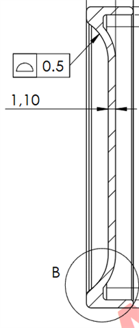
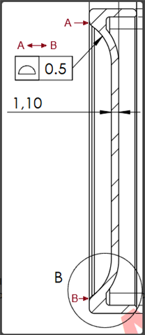
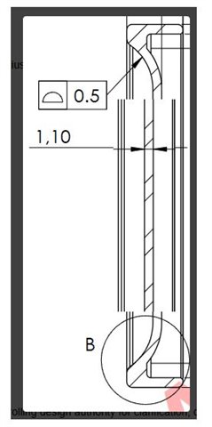
Today i had to check a profile callout (0.5 max - form only), but i find the results a bit strange, maybe i'm missing something but here is what i got :

- Profile is reporting OOT while point cloud colormap shows pretty good values (tolerance set to +/-0.25) while T-value shows something even different :


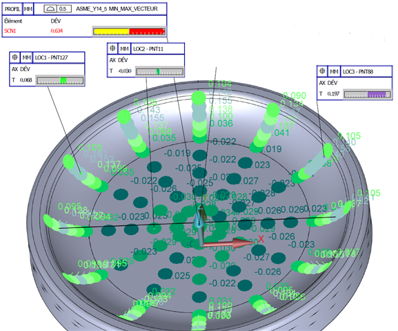
Where is the truth here ?

I would have think the values shown on point cloud are equal to the T-value no ?

For example here the point 88 is reporting 0.140 and T-value is 0.197, point 127 is reporting 0.152 and T-value is 0.068...

Also, if i look at all the values shown, the min is -0.034 and max is 0.155 so i would assume the profile result would be 0.189.

Any idea ?

Parents
  • All points are here, and graphical analysis looks like this :

    External points looks all OOT.

    Here is the callout, so it's bilateral, and i'm pretty sure the engineer just want the big radius to be well shaped:

  • In my opinion, that callout is ambiguous.  If it were me, I would ether bug controlling design authority for clarification, or just move forward with interpreting it at face value: exclusively interpret it to apply to the radius, which is continuous, to become a donut.  This is inherently controlled "all around", BUT clearly defined as a bilateral zone, ±0.25mm from the radius nominal.

    So if it were me, I would do the following:
    1: remove analysis of the base plane inside the cup.
    2: prudently exclude blend radii at top of cup.
    3: measure it as individual radii, then construct a scan set of all the radii combined, bestfit align to the combined radii set, then produce one profile of a surface to that set.

  • but why measure as individual radii? 

    why not measure the flat/plane, level and origin, inspect profile/radii as shown with scans, and report the profile? what does best fitting to the radii do?

  • Paste with pattern FTW! 
    If there are datums on the part perhaps be aligned to them, I get trying to best fit to the radius itself but that is rarely what the enginerds intend when they call it out like that. They would typically say they want it comparted to the nominal model location, which when you machine the part the datums establish the nominal model location in reality. Checking it to a datum will also allow you to give the machinist meaningful feedback about their part thus allowing them to make corrections. 

    Definitely steer WAY clear of the start/stop of the radius for your pickups though, that will throw things off. 

  • there arent datums on the part. EDIT: referenced on the drawing provided. 

  • well, since the flat/plane is not a defined datum, nor part of the feature of size being controlled... it's adding noise to the interpretation of the part and the software's ability to bestfit the profile measurement/interpretation as communicated on the drawing. 

    If you had a width measurement: would you level and datum to a potentially non-perpendicular plane, before measuring that width? why not?  (It's rhetorical, you wouldn't because it can introduce error in your resultant values if the (incorrectly applied) datum plane skews your distance.)

  • yes but the plane can be a known value since you can measure the thickness. using the plane as a stable feature to base the rest of the profile off of isn't an unreasonable method of evaluating the rest of the profile. 

  • I agree with  , based on that drawing, I wouldn't  have included the plane for the profile measurement because the leader line only points to the radius and does not include the all around symbol. 

    Either way (whether you include the plane or not), you need to do a full 3D best-fit alignment using the vector min/max fit on all of your measured points before reporting T values or creating the point colormap.  Only then would the results be equivalent to a legacy form only profile (again with the vector min/max fit) or a geometric tolerance profile command.

  • the leader line points to a line on a cross section and doesnt start or stop anywhere, meaning its the entire surface. you can't jsut ignore the plane hahaha

  • I disagree.  ASME say this...

    As it stands, the drawing is ambiguous at the very least.  If they want to include the planar section as well as the radius, they should add the between symbology.  Something like this...

  • so y'all would stop where the radius ends and the plane begins? that's wild but suit yourself. 

    you would accept a part with a step on the plane because the radius profile was good? that makes no sense to me. 

  • I'm not saying it makes sense.  I'm saying that, as it stands, and as per the rules of ASME, the drawing does not explicitly control that kind of scenario.  This is a perfect example of why design engineers need to have a better understanding of GDT and need to ensure they clearly define everything in accordance with whichever standard they are working to.  We, as inspectors should not need to second guess what the designer intends, nor be forced to make judgement calls or apply our own interpretations when measuring parts.  It becomes even more important as companies transition form the traditional 2D drawing approach to full model based definition - computers cannot guess, they need one single, clear interpretation and well defined rules that they can follow.

Reply
  • I'm not saying it makes sense.  I'm saying that, as it stands, and as per the rules of ASME, the drawing does not explicitly control that kind of scenario.  This is a perfect example of why design engineers need to have a better understanding of GDT and need to ensure they clearly define everything in accordance with whichever standard they are working to.  We, as inspectors should not need to second guess what the designer intends, nor be forced to make judgement calls or apply our own interpretations when measuring parts.  It becomes even more important as companies transition form the traditional 2D drawing approach to full model based definition - computers cannot guess, they need one single, clear interpretation and well defined rules that they can follow.

Children