hexagon logo

Help with Profile of surface using FARO

I have a faro arm and we recently upgraded to PC-DMIS, still getting used to the software, I have encountered this one problem.. I have to measure the profile of a gasket surface. There are two things needed here,
1st- the profile of the gasket surface
2nd - height of "inspection points" from datum (A) in Z axis
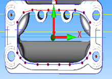
Now the inspection points are present on the CAD. The screen shot is attached.
I used "vector points" to construct the points as shown on the surface. The alignment was Iterative, using three datums, the gasket surface plane (A), the hole on the top left corner (B) and the hole on the bottom right corner (C). When I execute this program, the alignment looks ok, the plane and the circles align properly, but when I try and measure the vector points, the measured points somehow get projected away from the surface! Cannot figure out what I am doing wrong! Can anyone help me with this please? Thanks

AD

Attached Files
Parents

  • CIR1 =FEAT/CONTACT/CIRCLE,CARTESIAN,IN,LEAST_SQR
    THEO/<-1.6139,0.61, -0.2365>,<0.0043633,0,0.9999905>,0.28,0,360
    ACTL/<-0.3574,-2.1648,31.3494>,<-0.1152812,0.9887236,0.0955816>,0.2858,0,360
    TARG/<-1.6139,0.61,-0.2365>,<0.0043633,0,0.9999905>
    ANGLE VEC=<0.9999905,0,-0.0043633>
    DIRECTION=CCW
    SHOW FEATURE PARAMETERS=NO
    SHOW CONTACT PARAMETERS=YES
    NUMHITS=4,DEPTH=0,PITCH=0
    SAMPLE HITS=3,SPACER=0
    FIND HOLE=DISABLED,ONERROR=NO,READ POS=NO
    SHOW HITS=NOPNT1 =FEAT/CONTACT/VECTOR POINT,CARTESIAN
    THEO/<1.3859,0.4132, 0>,<0,0,1>
    ACTL/<1.394,0.3682,-0.0147>,<0,0,1>
    TARG/<1.3859,0.4132,0>,<0,0,1>
    SNAP=NO
    SHOW FEATURE PARAMETERS=NO
    SHOW CONTACT PARAMETERS=YES
    SHOW HITS=NO
    PNT2 =FEAT/CONTACT/VECTOR POINT,CARTESIAN
    THEO/<1.1478,0.6815, 0.0056>,<0.0215792,0,0.9997671>
    ACTL/<1.191,0.6617,-0.0567>,<0.0215792,0,0.9997671>
    TARG/<1.1478,0.6815,0.0056>,<0.0215792,0,0.9997671>
    SNAP=NO
    SHOW FEATURE PARAMETERS=NO
    SHOW CONTACT PARAMETERS=YES
    SHOW HITS=NO


    Why aren't all these nominals 0 like PNT1 is? Is the nominal Gasket surface not flat? It looks bowed in the measured points for your plane, but not as much as what the nominal for CIR1 suggests. I still don't like the Plane for the iterative alignment, but if that Z height for CIR1 is wrong, it will skew the entire gasket surface after the iterative alignment.

    What was the Theoretical thickness that it was set to adidesh?
Reply

  • CIR1 =FEAT/CONTACT/CIRCLE,CARTESIAN,IN,LEAST_SQR
    THEO/<-1.6139,0.61, -0.2365>,<0.0043633,0,0.9999905>,0.28,0,360
    ACTL/<-0.3574,-2.1648,31.3494>,<-0.1152812,0.9887236,0.0955816>,0.2858,0,360
    TARG/<-1.6139,0.61,-0.2365>,<0.0043633,0,0.9999905>
    ANGLE VEC=<0.9999905,0,-0.0043633>
    DIRECTION=CCW
    SHOW FEATURE PARAMETERS=NO
    SHOW CONTACT PARAMETERS=YES
    NUMHITS=4,DEPTH=0,PITCH=0
    SAMPLE HITS=3,SPACER=0
    FIND HOLE=DISABLED,ONERROR=NO,READ POS=NO
    SHOW HITS=NOPNT1 =FEAT/CONTACT/VECTOR POINT,CARTESIAN
    THEO/<1.3859,0.4132, 0>,<0,0,1>
    ACTL/<1.394,0.3682,-0.0147>,<0,0,1>
    TARG/<1.3859,0.4132,0>,<0,0,1>
    SNAP=NO
    SHOW FEATURE PARAMETERS=NO
    SHOW CONTACT PARAMETERS=YES
    SHOW HITS=NO
    PNT2 =FEAT/CONTACT/VECTOR POINT,CARTESIAN
    THEO/<1.1478,0.6815, 0.0056>,<0.0215792,0,0.9997671>
    ACTL/<1.191,0.6617,-0.0567>,<0.0215792,0,0.9997671>
    TARG/<1.1478,0.6815,0.0056>,<0.0215792,0,0.9997671>
    SNAP=NO
    SHOW FEATURE PARAMETERS=NO
    SHOW CONTACT PARAMETERS=YES
    SHOW HITS=NO


    Why aren't all these nominals 0 like PNT1 is? Is the nominal Gasket surface not flat? It looks bowed in the measured points for your plane, but not as much as what the nominal for CIR1 suggests. I still don't like the Plane for the iterative alignment, but if that Z height for CIR1 is wrong, it will skew the entire gasket surface after the iterative alignment.

    What was the Theoretical thickness that it was set to adidesh?
Children
No Data