hexagon logo

Help with Profile of surface using FARO

I have a faro arm and we recently upgraded to PC-DMIS, still getting used to the software, I have encountered this one problem.. I have to measure the profile of a gasket surface. There are two things needed here,
1st- the profile of the gasket surface
2nd - height of "inspection points" from datum (A) in Z axis
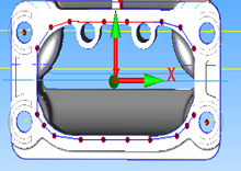
Now the inspection points are present on the CAD. The screen shot is attached.
I used "vector points" to construct the points as shown on the surface. The alignment was Iterative, using three datums, the gasket surface plane (A), the hole on the top left corner (B) and the hole on the bottom right corner (C). When I execute this program, the alignment looks ok, the plane and the circles align properly, but when I try and measure the vector points, the measured points somehow get projected away from the surface! Cannot figure out what I am doing wrong! Can anyone help me with this please? Thanks

AD

Attached Files
  • I wouldn't use that plane for an iterative alignment. Someone correct me if I'm wrong, but the plane would be reduced to a single point that is the average center of the points used to create it, which would be roughly along the line created between B and C here. If you've taken B and C as Auto Circles and used sample hits, then using one of the other two remaining holes on that surface (or both) to build the iterative alignment would be more helpful. You're not using the other holes for Rotate or Origin, only to level the plane.

    Can you post some code plz.
  • One more thing to check here. Make sure that when ou build the vector points you don't have thickness turned on. In the edit window, select one of the vector points and press F9. Now take a look under the IJK vector for the point. Thickness should be set to none.

    And fill in your additional information so we know what version you're working with.
  • Kami,

    I checked the vector points and the thickness was set to theoretical, changed it to none. the version of the software is 4.3 and i am using it on a FARO platinum arm. here is a part of the code
    PLN1 =FEAT/PLANE,CARTESIAN,TRIANGLE
    THEO/<-0.0275,-0.0127,0.0058>,<-0.0005738,0.0003179,0.9999998>
    ACTL/<1.0628,-2.0565,30.7093>,<-0.0149585,0.9998409,-0.0097155>
    MEAS/PLANE,8
    HIT/BASIC,NORMAL,<-1.5133,-0.0007,0>,<-0.0005732,0.0003178,0.9999998>,<0.1355,-2.0684,31.6828>,USE THEO=YES
    HIT/BASIC,NORMAL,<-1.319,0.5572,0.0017>,<-0.0005732,0.0003178,0.9999998>,<-0.1382,-2.0703,31.1638>,USE THEO=YES
    HIT/BASIC,NORMAL,<0.0048,0.7934,0.018>,<-0.0005732,0.0003178,0.9999998>,<0.6049,-2.0517,30.0105>,USE THEO=YES
    HIT/BASIC,NORMAL,<1.2872,0.5396,0.0024>,<-0.0005732,0.0003178,0.9999998>,<1.8011,-2.0683,29.2146>,USE THEO=YES
    HIT/BASIC,NORMAL,<1.4922,-0.0022,0>,<-0.0005732,0.0003178,0.9999998>,<2.1462,-2.0633,29.4371>,USE THEO=YES
    HIT/BASIC,NORMAL,<1.1743,-0.6652,0.005>,<-0.0005732,0.0003178,0.9999998>,<1.7425,-2.0333,31.0968>,USE THEO=YES
    HIT/BASIC,NORMAL,<-0.0103,-0.7741,0.018>,<-0.0005732,0.0003178,0.9999998>,<1.6575,-2.0324,31.1808>,USE THEO=YES
    HIT/BASIC,NORMAL,<-1.3358,-0.5492,0.0012>,<-0.0005732,0.0003178,0.9999998>,<0.5526,-2.0647,31.8882>,USE THEO=YES
    ENDMEAS/
    CIR1 =FEAT/CONTACT/CIRCLE,CARTESIAN,IN,LEAST_SQR
    THEO/<-1.6139,0.61,-0.2365>,<0.0043633,0,0.9999905>,0.28,0,360
    ACTL/<-0.3574,-2.1648,31.3494>,<-0.1152812,0.9887236,0.0955816>,0.2858,0,360
    TARG/<-1.6139,0.61,-0.2365>,<0.0043633,0,0.9999905>
    ANGLE VEC=<0.9999905,0,-0.0043633>
    DIRECTION=CCW
    SHOW FEATURE PARAMETERS=NO
    SHOW CONTACT PARAMETERS=YES
    NUMHITS=4,DEPTH=0,PITCH=0
    SAMPLE HITS=3,SPACER=0
    FIND HOLE=DISABLED,ONERROR=NO,READ POS=NO
    SHOW HITS=NO
    CIR2 =FEAT/CONTACT/CIRCLE,CARTESIAN,IN,LEAST_SQR
    THEO/<1.6151,-0.532,0.0006>,<0.0043633,0,0.9999905>,0.28,0,360
    ACTL/<2.6385,-2.1773,29.6891>,<-0.1511636,0.9884376,-0.011863>,0.2856,0,360
    TARG/<1.6151,-0.532,0.0006>,<0.0043633,0,0.9999905>
    ANGLE VEC=<0.9999905,0,-0.0043633>
    DIRECTION=CCW
    SHOW FEATURE PARAMETERS=NO
    SHOW CONTACT PARAMETERS=YES
    NUMHITS=4,DEPTH=0,PITCH=0
    SAMPLE HITS=3,SPACER=0
    FIND HOLE=DISABLED,ONERROR=NO,READ POS=NO
    SHOW HITS=NO
    A1 =ALIGNMENT/START,RECALL:STARTUP,LIST=YES
    ALIGNMENT/ITERATE
    PNT TARGET RAD=0.1969,START LABEL=,FIXTURE TOL=0,ERROR LABEL=
    MEAS ALL FEAT=NO,MAX ITERATIONS=99,LEVEL AXIS=YAXIS,ROTATE AXIS=ZAXIS,ORIGIN AXIS=XAXIS
    LEVEL=PLN1,CIR1,CIR2,,
    ROTATE=CIR1,CIR2,,
    ORIGIN=CIR1,,
    ALIGNMENT/END
    DATDEF/FEATURE=PLN1,A
    DATDEF/FEATURE=CIR1,B
    DATDEF/FEATURE=CIR2,C
    PNT1 =FEAT/CONTACT/VECTOR POINT,CARTESIAN
    THEO/<1.3859,0.4132,0>,<0,0,1>
    ACTL/<1.394,0.3682,-0.0147>,<0,0,1>
    TARG/<1.3859,0.4132,0>,<0,0,1>
    SNAP=NO
    SHOW FEATURE PARAMETERS=NO
    SHOW CONTACT PARAMETERS=YES
    SHOW HITS=NO
    PNT2 =FEAT/CONTACT/VECTOR POINT,CARTESIAN
    THEO/<1.1478,0.6815,0.0056>,<0.0215792,0,0.9997671>
    ACTL/<1.191,0.6617,-0.0567>,<0.0215792,0,0.9997671>
    TARG/<1.1478,0.6815,0.0056>,<0.0215792,0,0.9997671>
    SNAP=NO
    SHOW FEATURE PARAMETERS=NO
    SHOW CONTACT PARAMETERS=YES
    SHOW HITS=NO

    it goes on till point 18 and then i have the profile call out. I will try this again with the thickness turned off and see what the results are. Thanks

    AD

  • CIR1 =FEAT/CONTACT/CIRCLE,CARTESIAN,IN,LEAST_SQR
    THEO/<-1.6139,0.61, -0.2365>,<0.0043633,0,0.9999905>,0.28,0,360
    ACTL/<-0.3574,-2.1648,31.3494>,<-0.1152812,0.9887236,0.0955816>,0.2858,0,360
    TARG/<-1.6139,0.61,-0.2365>,<0.0043633,0,0.9999905>
    ANGLE VEC=<0.9999905,0,-0.0043633>
    DIRECTION=CCW
    SHOW FEATURE PARAMETERS=NO
    SHOW CONTACT PARAMETERS=YES
    NUMHITS=4,DEPTH=0,PITCH=0
    SAMPLE HITS=3,SPACER=0
    FIND HOLE=DISABLED,ONERROR=NO,READ POS=NO
    SHOW HITS=NOPNT1 =FEAT/CONTACT/VECTOR POINT,CARTESIAN
    THEO/<1.3859,0.4132, 0>,<0,0,1>
    ACTL/<1.394,0.3682,-0.0147>,<0,0,1>
    TARG/<1.3859,0.4132,0>,<0,0,1>
    SNAP=NO
    SHOW FEATURE PARAMETERS=NO
    SHOW CONTACT PARAMETERS=YES
    SHOW HITS=NO
    PNT2 =FEAT/CONTACT/VECTOR POINT,CARTESIAN
    THEO/<1.1478,0.6815, 0.0056>,<0.0215792,0,0.9997671>
    ACTL/<1.191,0.6617,-0.0567>,<0.0215792,0,0.9997671>
    TARG/<1.1478,0.6815,0.0056>,<0.0215792,0,0.9997671>
    SNAP=NO
    SHOW FEATURE PARAMETERS=NO
    SHOW CONTACT PARAMETERS=YES
    SHOW HITS=NO


    Why aren't all these nominals 0 like PNT1 is? Is the nominal Gasket surface not flat? It looks bowed in the measured points for your plane, but not as much as what the nominal for CIR1 suggests. I still don't like the Plane for the iterative alignment, but if that Z height for CIR1 is wrong, it will skew the entire gasket surface after the iterative alignment.

    What was the Theoretical thickness that it was set to adidesh?
  • Kami,

    The gasket surface is not flat. It has a "Crown" that makes a bow on the top and the bottom surfaces. On the vector points, the Z distance keeps changing, so these points become my inspection points. As you will notice, there is quite a bit of deviation in the distances. The theoretical thickness was actually on zero for the points. You have highlighted the Z value for circle 1. Should the value have been zero?
  • You have highlighted the Z value for circle 1. Should the value have been zero?


    You tell me. You have the CAD.

    And since there's a crown in that surface, it's not very useful for a plane. I would stress again to use the other two holes on that surface in addition to B and C to build your iterative alignment off of. I will copy, pasteand edit your code from above to show a rough idea of what I mean. I may not be correct on the coordinates for the holes though.
  • pln1 was removed. It can be constructed below. See note below.
    cir1 =feat/contact/circle,cartesian,in,least_sqr
    theo/<-1.6139,0.61,-0.2365>,<0.0043633,0,0.9999905>,0.28,0,360
    actl/<-0.3574,-2.1648,31.3494>,<-0.1152812,0.9887236,0.0955816>,0.2858,0,360
    targ/<-1.6139,0.61,-0.2365>,<0.0043633,0,0.9999905>
    angle vec=<0.9999905,0,-0.0043633>
    direction=ccw
    show feature parameters=no
    show contact parameters=yes
    numhits=4,depth=0,pitch=0
    sample hits=3,spacer=0
    find hole=disabled,onerror=no,read pos=no
    show hits=no
    cir2 =feat/contact/circle,cartesian,in,least_sqr
    theo/<1.6151,-0.532,0.0006>,<0.0043633,0,0.9999905>,0.28,0,360
    actl/<2.6385,-2.1773,29.6891>,<-0.1511636,0.9884376,-0.011863>,0.2856,0,360
    targ/<1.6151,-0.532,0.0006>,<0.0043633,0,0.9999905>
    angle vec=<0.9999905,0,-0.0043633>
    direction=ccw
    show feature parameters=no
    show contact parameters=yes
    numhits=4,depth=0,pitch=0
    sample hits=3,spacer=0
    find hole=disabled,onerror=no,read pos=no
    show hits=no
    cir3 =feat/contact/circle,cartesian,in,least_sqr
    theo/<-1.6139,-0.532,-0.2365>,<0.0043633,0,0.9999905>,0.28,0,360
    actl/<-0.3574,-2.1648,31.3494>,<-0.1152812,0.9887236,0.0955816>,0.2858,0,360
    targ/<-1.6139,-0.532,-0.2365>,<0.0043633,0,0.9999905>
    angle vec=<0.9999905,0,-0.0043633>
    direction=ccw
    show feature parameters=no
    show contact parameters=yes
    numhits=4,depth=0,pitch=0
    sample hits=3,spacer=0
    find hole=disabled,onerror=no,read pos=no
    show hits=no
    cir4 =feat/contact/circle,cartesian,in,least_sqr
    theo/<1.6151,0.61,0.0006>,<0.0043633,0,0.9999905>,0.28,0,360
    actl/<2.6385,-2.1773,29.6891>,<-0.1511636,0.9884376,-0.011863>,0.2856,0,360
    targ/<1.6151,0.61,0.0006>,<0.0043633,0,0.9999905>
    angle vec=<0.9999905,0,-0.0043633>
    direction=ccw
    show feature parameters=no
    show contact parameters=yes
    numhits=4,depth=0,pitch=0
    sample hits=3,spacer=0
    find hole=disabled,onerror=no,read pos=no
    show hits=no

    a1 =alignment/start,recall:startup,list=yes
    alignment/iterate
    pnt target rad=0.1969,start label=,fixture tol=0,error label=
    meas all feat=no,max iterations=99,level axis=yaxis,rotate axis=zaxis,origin axis=xaxis
    level=cir1,cir2, cir3,cir4,,
    rotate=cir1,cir2,,
    origin=cir1,,
    alignment/end
    if you want a plane still for datum a you can construct a plane from the 4 circles. Then you can leave the line below.
    datdef/feature=pln1,a
    datdef/feature=cir1,b
    datdef/feature=cir2,c
    pnt1 =feat/contact/vector point,cartesian
    theo/<1.3859,0.4132,0>,<0,0,1>
    actl/<1.394,0.3682,-0.0147>,<0,0,1>
    targ/<1.3859,0.4132,0>,<0,0,1>
    snap=no
    show feature parameters=no
    show contact parameters=yes
    show hits=no
    pnt2 =feat/contact/vector point,cartesian
    theo/<1.1478,0.6815,0.0056>,<0.0215792,0,0.9997671>
    actl/<1.191,0.6617,-0.0567>,<0.0215792,0,0.9997671>
    targ/<1.1478,0.6815,0.0056>,<0.0215792,0,0.9997671>
    snap=no
    show feature parameters=no
    show contact parameters=yes
    show hits=no