hexagon logo

Profile Tolerance

Hello All,

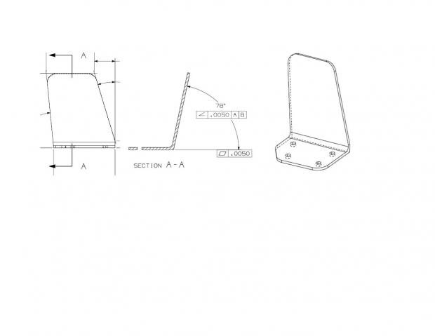
I have a part that the drawing only given a couple of FCF for True Position for 4 holes, Angle related to Datum A B &C and a profile tolerance of .030. I have to use a CAD model for inspection.

I was able inspecting the holes. For the remaining periphery of the parts, have been told because Profile Tolerance was given, I have to use a feature in PC-DMIS to inspect the periphery of the part, include angles. Please see the picture attached.

I am newbie to Romer Arm and PC-DMIS and working Profile Tolerance. Your guidance is greatly appreciated.


Parents
  • What you are describing is how I wish all parts were defined.
    All you need to do is create a group of auto-vector points, collect them into a set (Constructed Feature Set) and then dimension the set with surface profile (form and location) with a tolerance of +/-.015.
    Activate textual and graphical analysis to view the deviations if needed.
Reply
  • What you are describing is how I wish all parts were defined.
    All you need to do is create a group of auto-vector points, collect them into a set (Constructed Feature Set) and then dimension the set with surface profile (form and location) with a tolerance of +/-.015.
    Activate textual and graphical analysis to view the deviations if needed.
Children
No Data