hexagon logo

Profile Tolerance

Hello All,

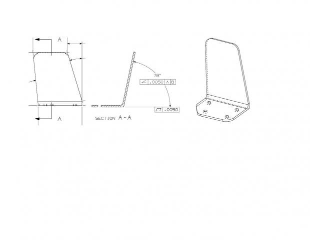
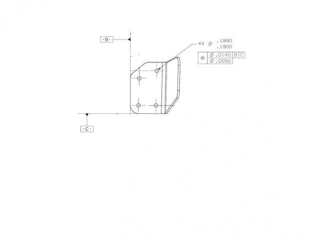
I have a part that the drawing only given a couple of FCF for True Position for 4 holes, Angle related to Datum A B &C and a profile tolerance of .030. I have to use a CAD model for inspection.

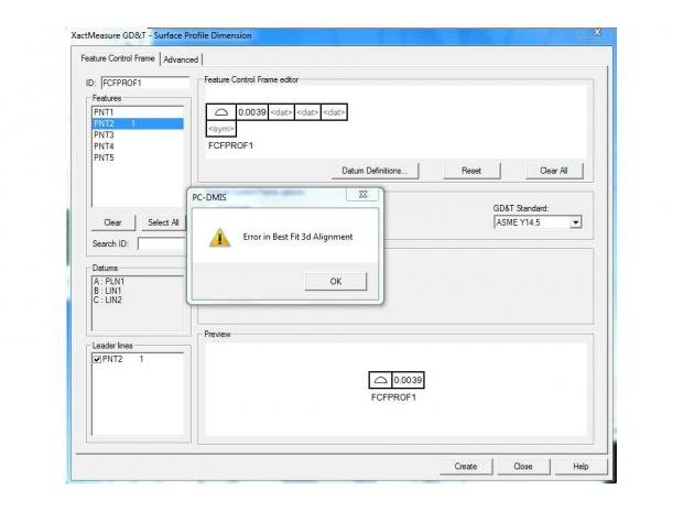
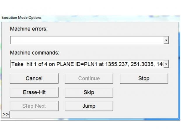
I was able inspecting the holes. For the remaining periphery of the parts, have been told because Profile Tolerance was given, I have to use a feature in PC-DMIS to inspect the periphery of the part, include angles. Please see the picture attached.

I am newbie to Romer Arm and PC-DMIS and working Profile Tolerance. Your guidance is greatly appreciated.


  • I am not seeing the profile that you are talking about. I see flatness which evaluates the form of the plane to itself but it is not relative to anything else. So unless there is a page missing there is not a profile check unless they want you to report the flatness as a profile of a surface form only. Should yield the same results but I would report the flatness as it is on the print.
  • Wicked_Tatto,

    Thanks for your quick respond. The Surface Profile Tolerance called out on General Note, "THE LOCATION OF ALL PART FEATURES ARE SUBJECT TO A SURFACE PROFILE TOLERANCE ZONE OF .0300 WITH RESPECT TO THE PRIMARY DATUM A, SECONDARY DATUM B, AND THE TERTIARY DATUM C". Also attached is another picture which showing Datum B and C. The drawing is none dimensional and only show FCF and I have to inspect to CAD model.

    Thanks

    MT
  • What you are describing is how I wish all parts were defined.
    All you need to do is create a group of auto-vector points, collect them into a set (Constructed Feature Set) and then dimension the set with surface profile (form and location) with a tolerance of +/-.015.
    Activate textual and graphical analysis to view the deviations if needed.
  • John,

    I was able using the vector point and created group and used surface profile for dimensioning. Then the system crashed on me so I have to start over and not sure how did the first time. What I am stuck right now is grouping all of the Vector in set for surface profile dimensioing.

    Here the steps

    1) Alignment (CAD and Part to CAD Model)
    2) Defined Datum Plan A B &C
    3) Selected Point Only Mode
    4) Hit point on part surfaces
    5) Selected all hit points in Edit Windows
    6) Selected Surface Profile dimensioning
    7) Try to select all hit points and assign to datum plan, but PC-DMIS popup with "Error in best fit 3r alignment" and repeat 3 time and in only let pick single instead of group to set FCF. Please see attached image and let me know what I did wrong or missing

    Also when I hit control Q to do the alignment of the part, the popup box appears with "Machine Error". Please see attached and let me know if it is normal I did some wrong.

    Your help is greatly appreaciate

  • Once you have a group of points you want to include in the set:

    Insert -> Feature -> Constructed -> Set
    Then choose the points you want in the set from the dropdown menu that pops up.

    Then you just dimension the set with Surface Profile:
    Insert -> Dimension -> Profile -> Surface

    Make sure you chave Form And Location checked.
    Set the tolerances at +.015 and -.015

    Check Textual and Graphical analysis to see the details of each point in the report.

    By the way, what I have described is the Legacy method. Johnny doan play no xact measure.
  • John,

    I was able using the vector point and created group and used surface profile for dimensioning. Then the system crashed on me so I have to start over and not sure how did the first time. What I am stuck right now is grouping all of the Vector in set for surface profile dimensioing.

    Here the steps

    1) Alignment (CAD and Part to CAD Model)
    2) Defined Datum Plan A B &C
    3a) Create a Point AutoTrigger Command with 'On' and 'Beeping On' selected (under F10)
    3b) Open the Auto Vector Point Dialog Box
    3c) Click many AV Points on the model
    3d) Create another Point AutoTrigger Command with 'Off' selected under F10
    4) Create a Constructed Feature Set
    5) Choose all your AV Points
    6) Create a Profile Dimension
    7) Define your Datums A,B,C with the 'Datum Definition' button
    8) Build your FCF like on the drawing
    9) Execute


    Also when I hit control Q to do the alignment of the part, the popup box appears with "Machine Error". Please see attached and let me know if it is normal I did some wrong.

    Your help is greatly appreaciate


    Those are steps you should have done. Measured Points aren't going to work, you need Auto Vector Points. The error message you saw will persist until you put in the Datum Reference Frame of ABC in the Profile Dimension.