hexagon logo

Profile Tolerance

Hello All,

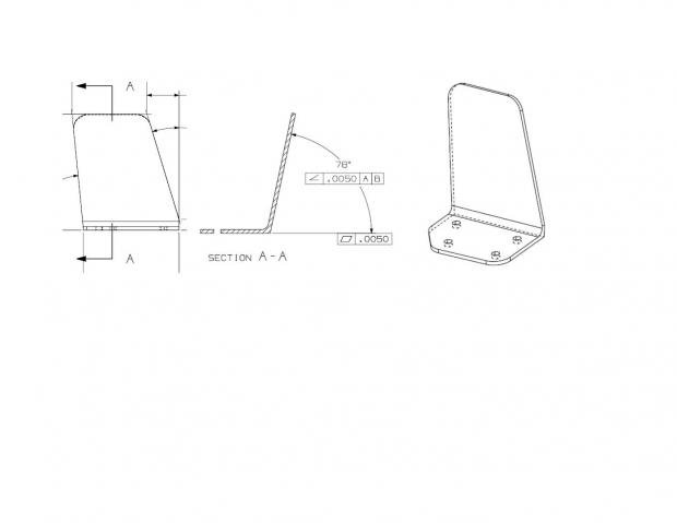
I have a part that the drawing only given a couple of FCF for True Position for 4 holes, Angle related to Datum A B &C and a profile tolerance of .030. I have to use a CAD model for inspection.

I was able inspecting the holes. For the remaining periphery of the parts, have been told because Profile Tolerance was given, I have to use a feature in PC-DMIS to inspect the periphery of the part, include angles. Please see the picture attached.

I am newbie to Romer Arm and PC-DMIS and working Profile Tolerance. Your guidance is greatly appreciated.


Parents
  • Once you have a group of points you want to include in the set:

    Insert -> Feature -> Constructed -> Set
    Then choose the points you want in the set from the dropdown menu that pops up.

    Then you just dimension the set with Surface Profile:
    Insert -> Dimension -> Profile -> Surface

    Make sure you chave Form And Location checked.
    Set the tolerances at +.015 and -.015

    Check Textual and Graphical analysis to see the details of each point in the report.

    By the way, what I have described is the Legacy method. Johnny doan play no xact measure.
Reply
  • Once you have a group of points you want to include in the set:

    Insert -> Feature -> Constructed -> Set
    Then choose the points you want in the set from the dropdown menu that pops up.

    Then you just dimension the set with Surface Profile:
    Insert -> Dimension -> Profile -> Surface

    Make sure you chave Form And Location checked.
    Set the tolerances at +.015 and -.015

    Check Textual and Graphical analysis to see the details of each point in the report.

    By the way, what I have described is the Legacy method. Johnny doan play no xact measure.
Children
No Data