hexagon logo

Iterative Alignment Error

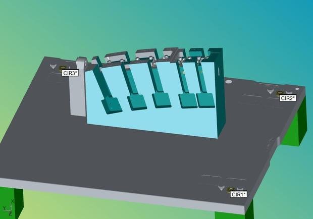
Hey, friends. Hoping someone can help me. I keep getting an 'Iterative Alignment Error' on my programs and I'm not sure why... I've attached my code and a picture of the CAD I'm working with.

I'm aligning on 3 sample hits on top of 3 bushings pointing in the x
I'm rotating in two bushings into the Z
I'm using one bushing for the origin.

I don't know why it isn't working Disappointed

Save meeeeeeeeeee


  • That's an interesting output... Try this instead:

    Copy your code on the edit screen from cir1 to the end of the iterative alignment. (Ctrl + C). Paste it into the reply window (Ctrl + V). Put
    infront of your code, and
    after your code (delete the spaces inside the brackets.) It will look like:

    here's my code


    On second thought, I see the problem. You're rotating to Cir1 and Cir2 to Z. You can either rotate to Cir2 and 3 to Z, or rotate Cir1 and 2 to Y.

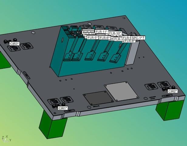
    Is Cir2 designated as bushing 2 on the piece? Usually the 90 degree corner is #1 (origin), the longer leg has #2 (rotate) and the shorter leg has the #3 (level).
  • CIR1       =FEAT/CONTACT/CIRCLE/DEFAULT,CARTESIAN,IN,LEAST_SQR
                THEO/<3573.806,275,-150>,<1,0,0>,9.525
                ACTL/<3573.806,275,-150>,<1,0,0>,9.525
                TARG/<3573.806,275,-150>,<1,0,0>
                START ANG=0,END ANG=360
                ANGLE VEC=<0,0,-1>
                DIRECTION=CCW
                SHOW FEATURE PARAMETERS=NO
                SHOW CONTACT PARAMETERS=YES
                  NUMHITS=4,DEPTH=2,PITCH=0
                  SAMPLE METHOD=SAMPLE_HITS
                  SAMPLE HITS=3,SPACER=3
                  FIND HOLE=DISABLED,ONERROR=NO,READ POS=NO
                SHOW HITS=NO
    DIM LOC1= LOCATION OF CIRCLE CIR1  UNITS=MM ,$
    GRAPH=OFF  TEXT=OFF  MULT=10.00  OUTPUT=BOTH  HALF ANGLE=NO
    AX    NOMINAL       MEAS       +TOL       -TOL        DEV     OUTTOL
    X     3573.806   3573.806      0.100      0.100      0.000      0.000 ----#----
    Y      275.000    275.000      0.100      0.100      0.000      0.000 ----#----
    Z     -150.000   -150.000      0.100      0.100      0.000      0.000 ----#----
    D        9.525      9.525      0.100      0.100      0.000      0.000 ----#----
    END OF DIMENSION LOC1
    CIR2       =FEAT/CONTACT/CIRCLE/DEFAULT,CARTESIAN,IN,LEAST_SQR
                THEO/<3573.806,825,-150>,<1,0,0>,9.525
                ACTL/<3573.806,825,-150>,<1,0,0>,9.525
                TARG/<3573.806,825,-150>,<1,0,0>
                START ANG=0,END ANG=360
                ANGLE VEC=<0,0,-1>
                DIRECTION=CCW
                SHOW FEATURE PARAMETERS=NO
                SHOW CONTACT PARAMETERS=YES
                  NUMHITS=4,DEPTH=2,PITCH=0
                  SAMPLE METHOD=SAMPLE_HITS
                  SAMPLE HITS=3,SPACER=3
                  FIND HOLE=DISABLED,ONERROR=NO,READ POS=NO
                SHOW HITS=NO
    DIM LOC2= LOCATION OF CIRCLE CIR2  UNITS=MM ,$
    GRAPH=OFF  TEXT=OFF  MULT=10.00  OUTPUT=BOTH  HALF ANGLE=NO
    AX    NOMINAL       MEAS       +TOL       -TOL        DEV     OUTTOL
    X     3573.806   3573.806      0.100      0.100      0.000      0.000 ----#----
    Y      825.000    825.000      0.100      0.100      0.000      0.000 ----#----
    Z     -150.000   -150.000      0.100      0.100      0.000      0.000 ----#----
    D        9.525      9.525      0.100      0.100      0.000      0.000 ----#----
    END OF DIMENSION LOC2
    CIR3       =FEAT/CONTACT/CIRCLE/DEFAULT,CARTESIAN,IN,LEAST_SQR
                THEO/<3573.806,275,300>,<1,0,0>,9.525
                ACTL/<3573.806,275,300>,<1,0,0>,9.525
                TARG/<3573.806,275,300>,<1,0,0>
                START ANG=0,END ANG=360
                ANGLE VEC=<0,0,-1>
                DIRECTION=CCW
                SHOW FEATURE PARAMETERS=NO
                SHOW CONTACT PARAMETERS=YES
                  NUMHITS=4,DEPTH=2,PITCH=0
                  SAMPLE METHOD=SAMPLE_HITS
                  SAMPLE HITS=3,SPACER=3
                  FIND HOLE=DISABLED,ONERROR=NO,READ POS=NO
                SHOW HITS=NO
    DIM LOC3= LOCATION OF CIRCLE CIR3  UNITS=MM ,$
    GRAPH=OFF  TEXT=OFF  MULT=10.00  OUTPUT=BOTH  HALF ANGLE=NO
    AX    NOMINAL       MEAS       +TOL       -TOL        DEV     OUTTOL
    X     3573.806   3573.806      0.100      0.100      0.000      0.000 ----#----
    Y      275.000    275.000      0.100      0.100      0.000      0.000 ----#----
    Z      300.000    300.000      0.100      0.100      0.000      0.000 ----#----
    D        9.525      9.525      0.100      0.100      0.000      0.000 ----#----
    END OF DIMENSION LOC3
    A1         =ALIGNMENT/START,RECALL:STARTUP,LIST=YES
                  ALIGNMENT/ITERATE
                    PNT TARGET RAD=5,START LABEL=,FIXTURE TOL=0.05,ERROR LABEL=
                    MEAS ALL FEAT=NO,LEVEL AXIS=XAXIS,ROTATE AXIS=ZAXIS,ORIGIN AXIS=YAXIS
                  LEVEL=CIR1,CIR2,CIR3,,
                  ROTATE=CIR1,CIR2,,
                  ORIGIN=CIR1,,
                ALIGNMENT/END
                COMMENT/REPT,
                REPORT ON FIXTURE BUILT TO CAD DATA IN MM
                SET UP WITH BUSHING HOLES AND BASE AS STAMPED.
                -----------------------------------------
                COMMENT/REPT,
                LOCATION - ORIGIN BUSHING HOLE
                ==============================
    DIM LOC1= LOCATION OF CIRCLE CIR1  UNITS=MM ,$
    GRAPH=OFF  TEXT=OFF  MULT=10.00  OUTPUT=BOTH  HALF ANGLE=NO
    AX    NOMINAL       MEAS       +TOL       -TOL        DEV     OUTTOL
    X     3573.806   3573.806      0.050      0.050      0.000      0.000 ----#----
    Y      275.000    275.000      0.050      0.050      0.000      0.000 ----#----
    Z     -150.000   -150.000      0.050      0.050      0.000      0.000 ----#----
    D        9.525      9.525      0.050      0.050      0.000      0.000 ----#----
    END OF DIMENSION LOC1
                COMMENT/REPT,
                LOCATION - ALIGN BUSHING HOLE
                =============================
    DIM LOC2= LOCATION OF CIRCLE CIR2  UNITS=MM ,$
    GRAPH=OFF  TEXT=OFF  MULT=10.00  OUTPUT=BOTH  HALF ANGLE=NO
    AX    NOMINAL       MEAS       +TOL       -TOL        DEV     OUTTOL
    X     3573.806   3573.806      0.050      0.050      0.000      0.000 ----#----
    Y      825.000    825.000      0.050      0.050      0.000      0.000 ----#----
    Z     -150.000   -150.000      0.050      0.050      0.000      0.000 ----#----
    D        9.525      9.525      0.050      0.050      0.000      0.000 ----#----
    END OF DIMENSION LOC2
                COMMENT/REPT,
                LOCATION - PLANE BUSHING HOLE
                =============================
    DIM LOC3= LOCATION OF CIRCLE CIR3  UNITS=MM ,$
    GRAPH=OFF  TEXT=OFF  MULT=10.00  OUTPUT=BOTH  HALF ANGLE=NO
    AX    NOMINAL       MEAS       +TOL       -TOL        DEV     OUTTOL
    X     3573.806   3573.806      0.050      0.050      0.000      0.000 ----#----
    Y      275.000    275.000      0.050      0.050      0.000      0.000 ----#----
    Z      300.000    300.000      0.050      0.050      0.000      0.000 ----#----
    D        9.525      9.525      0.050      0.050      0.000      0.000 ----#----
    END OF DIMENSION LOC3


    Sorry I labeled the bushings wrong... just did that up quickly for a picture... my bad.

    I'm leveling on all 3
    rotating on 1/2
    origin on 1


  • Ok, looking at your code and the new picture, I am not seeing anything wrong with what you're doing. Is it letting you measure the holes and then giving you the alignment error, or is it giving you the error upon creating the alignment? Is it just the "Iterative Alignment Error", or is it a "could not converge" or "Error: Deviation x.xxx"?

    1 thing that is odd, but should be irrelevant, is the 0.05 fixture tolerance. Since you are using 3, 2, 1 features, the fixture tolerance never comes into play, but that shouldn't be a showstopper.
  • He's leveling as well as rotating to the same features. Would that mess things up? In a less complex alignment...If I leveled to a plane in the Z+, I couldn't then rotate to that plane as well or an alignment error would be triggered.
  • No, with tooling balls or tooling holes, this is the standard procedure.

    Imagine having 3 pool balls glued to a table. Instead of a triangle to rack, we will use a square rack, but put a top on the rack. Put the rack down on the 3 balls, this levels the rack onto the 3 balls. Then pull one wall of the rack against 2 balls, this rotates to the 2 balls, but doesn't interfere with the level. Then pull an adjacent wall up against one of the 2 rotating balls, this stops the final translation and doesn't affect the level or rotate.
  • Interesting, I didn't know the software treated iterative alignments in this fashion. Thx for the info
  • I just get the prompt "Iterative Alignment Error". If I dimension my pickup features out after my alignment they have a weird "iq#####" something code in their values.

    Sometimes when I try to redo the alignment I'll select the 3-2-1 and when that's done and I go to hit ok to exit the iterative alignment, I get a "3 features must be select to plane on" error.... even though I clearly have 3 features selected.

    The fixture tolerance is just a default I never changed. Should I make it something different? Will it change my results at all?

    I even tried adding surface points off the base as my level and still get the same thing...
  • I don't think I've ever come across a situation like you're describing. I think what that's saying is that the values are extremely large.

    There's nothing in your code that looks wrong. The iterative is set up on the proper axes. The circles seems to be generated appropriately.

    What version of PC-DMIS? My only suggestion at this point is to try starting from scratch in a brand new program. Disappointed
  • Even when starting a new program; sometimes it works, sometimes it doesn't. There doesn't seem to be no reason as to what allows it to work properly vs what triggers the error.

    I'm using Pc DMIS portable 2016.

    Now I cry, right?
  • why are we bothering with an iterative alignment?

    Level to your points (once you've constructed a plane to actually Level to)
    Rotate from Cir1 to Cir2
    Origin to Cir1 in XY and plane in Z

    Done.

    If you don't want the part transformed, use "force alignment in car body" under F5. CAD Transformation avoided, but data and CAD are now registered.

    Basic alignment is good enough, here.