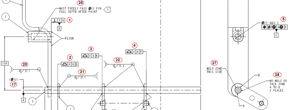
With reference to the print below, if I use the "Level Z+ to the cylinder" guideline, then in relation to the print, Z+ is pointing to the right (presuming vector directions). Then, it seems that the Datum B plane is PARALLEL to the [piece of paper] Datum A "plane", and therefore can't constrain rotation of the Z+ plane.
Now, the engineer insists that I'm wrong because the datum callout is to the AXIS of the cylinder, which is indeed perpendicular to Datum B.
My question is, how do I achieve this in PC-DMIS? If I construct a line in the Z+ workplane from A to C, and then use that to constrain the rotation, am I not effectively replacing Datum B with Datum C? Then Datum B simply becomes the place to put the Z origin.
How would you gurus approach this?
Another issue - the Datum C hole asks for A(M) - if Datum A is merely the axis line of the cylinder, can we even say it's a feature "of size"?
Also, would you probe Datum C as a cylinder, or as a circle with sample hits?