I am quite new to Laser scan.. Please advise quick and correct way to setup and check profile tolerance of the part using Laser scan on different type of material as Aluminum, Casting part...
Hardware:
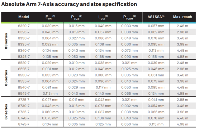
7 axis Absolute Romer Arm with Laser Scanner V3P/8525
SW:
PC-DMIS 24.12 CAD++ Scanning/MESH ARM /RDS latest version
Part:
1> Casting (profile tol. spec from +/-0.030"
2>Mixed Aluminum (profile tol. spec from +/-0.010")
3>Steel (profile tol. spec from +/-0.010"
Thanks so much
Hardware: 7 axis Absolute Romer Arm with Laser Scanner V3P/8525 SW: PC-DMIS 24.12 CAD++ Scanning/MESH ARM /RDS latest version Part: 1> Casting (profile tol. spec from +/-0.030" 2>Mixed Aluminum (profile tol. spec from +/-0.010") 3>Steel (profile tol. spec from +/-0.010"
[edited by: NikitaT at 7:18 PM (GMT -5) on May 15, 2025]