Can I vision probe be used to find the lowest point in a groove that is U shaped? or is that better suited for a tactile probe? I need to make sure this u shaped groove is centered between an ID and OD.
Offline with tactile, I can probe a small radius circle, construct a center point, probe the OD, then dimension the center point to the od subtracting the radius. Comes out good offline. Can I do the same thing with the vision probe?
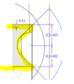
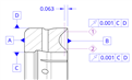
Ok, so my print changed. What the engineer wants to know now is the groove centered in between the ID and OD of this part. C is the ID and D is the OD. At 0.063in from surface B, construct 1 circle on each cone and check the run out of the circles to CD. Pcdmis only lets me choose either C or D and not both.
This is a ring. Attached is my print showing the cross section and the datums. Surface B isn't really there, its showing in the image because its a cross section. That groove is open. So where datum D and B should intersect, its basically a knife edge. Same goes for where C and B would intersect.
Because of this, I had to switch to tactile on my optiv to make D a cylinder. When I dimension runout on the constructed circles, it shows absolutely no deviation. I just want to make sure i'm doing anything wrong.
Plane A is probed, Level Zminus and Z orgin, Cylinder D is probed and XY orgin, nothing to hold rotation.
Dimension cylinder D, show deviation.
Probe C as a circle. Dimension, shows deviation.
Probe 1 cone and then the other.
Construct a circle on each cone.
Dimensions runout for each constructed circle and no deviation on runnout.