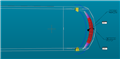
I have a tiny part to inspect and have to take the profile of the end of the tip (0.5mm width)
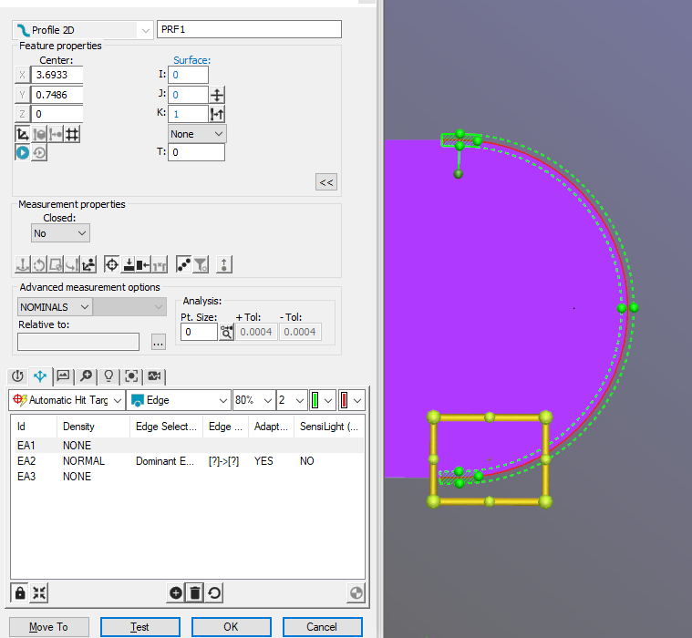
But, here is the thing, i've got my probed points:
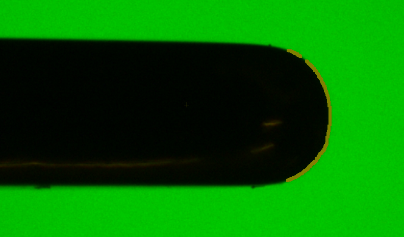
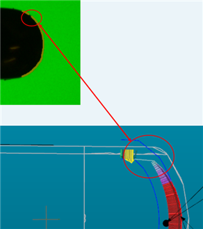
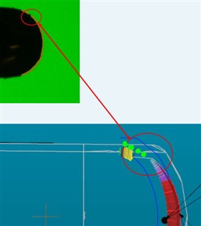
And here is what it looks like and the CAD:
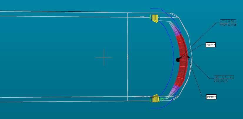
I don't understand why PCDMIS persists to take points i don't need (the yellow arrows).
As there isn't any datum, the profile can move into the tolerance zone but those points doesn't allow it and it results in non-conform part...
I tried to play with the filter but didn't find something really better.
Is there a way to better filter points ?
Attached Files