hexagon logo

Trying to build a disk probe with rollers

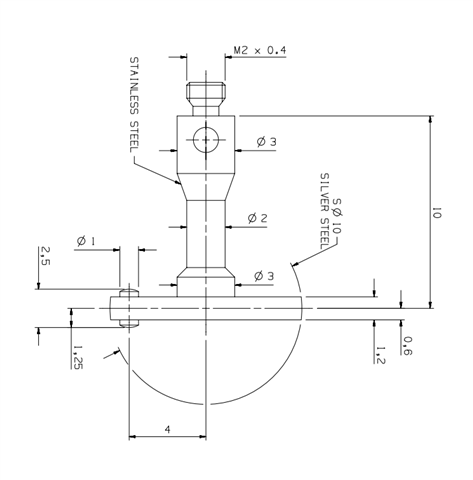
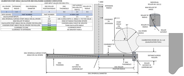
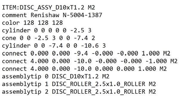
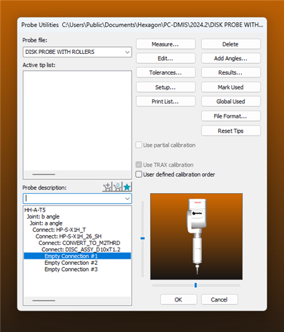
I'm not sure of the proper way to build a disk probe so that I'm able to use the rollers to measure groove width. I was told to add some offset point to the routine but that's not working. There has to be a way to build the probe so that the rollers are on there right? ive never built a probe from scratch so I may be lost in the procedure or even the capabilities. I have included a dwg of the disk to help. 

Parents Reply Children
  • Thanks unfortunately I have already gone through that route and due to my inexperience it is quite overwhelming. I may just need to give support a call and have then look over my shoulder. I appreciate the response and will continue my learning.

  • Mark,

    in that link, I have already made the common disc probes.

    all you need to do is copy the files to the correct directories as per the readme txt file and then the probes will appear in your probe components list.

    the trickier part is doing the calibration of the rollers. You will need a second calibration sphere that is small enough. The probe you wish to use only has a 4mm offset for the rollers, so calibrating the upper roller will require quite a small sphere.

  • Thanks so much for the reply. I feel I am talking to a celebrity as I've been reading your files for the past two days trying to figure it out. I think I understand the process and can't wait to try it out. Would you happen to know what size sphere I would need to get to be able to calibrate the rollers? Thanks again.

  • Ha ha. The only people that think I am a celebrity is my kids as I feature in a Youtube video for one of the products my work sells.

    If you re-download the excel file Disc_Probe_Calibration.xlsx  I have added a few missing discs like the one you are trying to use. I have saved it with the 10mm disc data input. I work out that you need a 2mm tip to act as your calibration sphere so that you don't hit the shank of the disc probe.

    If you let me know which version of PC-DMIS you are using, the head/sensor type etc, I can make you a sample probe for your probe build up.

     That 10mm disc is in my sample usrprobe.dat file.

  • I am using 2024.2. I copy and pasted the 10mm disc assy into the usrprobe.dat file as well as the 2.5 by 1 roller draw file into the c drive 2024.2 file. When I try to put the probe together I cannot find the last three connections from the drop-down list. the actual disk and the rollers a missing. I must have down something wrong or missed a step.

  • Mark,

    you need to copy all of the discs sub components into the usrprobe.dat.

    so you will need the 10mm disc and the 2.5mm rollers aswell.

    the assembly will make the whole disc as it has predefined components for its connections.

    just copy the entire sample usrprobe.dat i made and paste it into your version.

  • OK AWESOME! It worked i now have it all loaded, Thanks so much for your help. Now i have to figure out where to get a 2mm calibration sphere to use. can i use a 2mm styli that I have as long as I figure out a way to fix it to the table? Aby suggestions or website to buy the right sphere?

    P.S. The hexagon customer support person i have been talking to has eagerly tried to steer me away from checking groove height with a disk probe stating it won't be accurate. We were doing it with MCOSMOS without any issue. so, I'm sure this will be just fine. have you experienced any inconsistencies doing it this way? sure a star probe may be better but that's another probe change that will add up time over the course of thousands of parts.

  • the rollers have always been 'taught' as reference only things, not as a calibrated inspection item.  like, get it in the groove, touch bottom, touch top, use the mid-point as a relative elevation for using the disk.

    as for a sphere, don't waste your time searching for one, use a 2mm probe is the way to go.  all you need is a block with a 2mm tapped hole it in, mount the probe, use that.

  • Ok glad you got it to work.

    You can use a 2mm styli as the calibration sphere.

    Just make sure to teach the position of this “sphere” with your master probe before trying to calibrate the  rollers.

    if you calibrate the rollers properly, there is no reason it will not be accurate.

    in my own testing with a known calibration aretefact from a trimos height gage, basically a gage block stack that represents a groove or part of a Weber bar, I probed the width of the aretefact within 1um of the aretefacts calibration certificate. So if you take out the uncertainty/accuracy of the CMM, it measured perfect.