The before closed the cycle between the "given data in simufact" (= material properties from the Simufact material data base) and the "acquired data" (= simulation results of the compression test) by checking the numeric. The better this works, the better is the model (time stepping, friction approach, meshing, ....). If it would not work at all, our software would have a problem.
The second approach to validate your compression test simulation include the method and steps used to conduct from the simulated force-defection-curve to the flow curves of the material. If this is validated you can replace the simulated force-deflection-curve by a measured one and determine the flow curves to be used in the simulation.
This approach works better for a tension test because the (nearly) uniaxial deformation is bigger there. But the steps work with a compression test, too. I may want to stick to the unrealistic friction free constant temperature uniform strain rate simulation first, making the simulation more realistic in later steps coming closer to potential experiments. Which will make the next steps a bit more tricky and ambiguous.
Steps to do, check the Simufact Material Infosheet FlowCurves_en.pdf for some background information and formulas used:
Get the simulated force-defection-curve. About 5 points are fine. If applicable use the distance between 2 particles as "measurement length" for the deflection instead of using the stroke.
Calculate the engineering stresses and strains
Decided which of your points are close enough to a uniform deformation of the workpiece. One with these:
Calculate the true stress and strain
Plot true stress and true strain for the used strain rate and temperature.
Extrapolate the flow curve as applicable.
This is the "experimentally" determined flow curve of your material. It should be close to the flow curve used in the simulation of the experiment.
I can not share a temporary we-tranfer link in this Forum. The download is a zip-file. If you can unpack it to get the sfp file, the download is correct. Issues with opening the sfp-file are some thing different. It is version 2023.4.
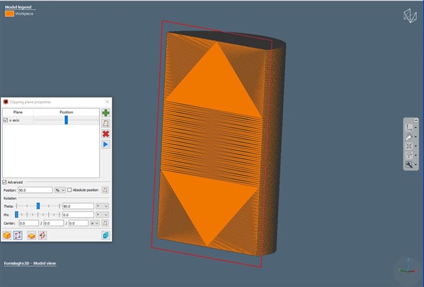
You are clipping the the model view. The model view contains the geometries used in the model as they have been imported or created as Basic Shapes, including the positioning applied later. Even if an initial mesh has been created for the workpiece, the model view will still contains only the geometry, not the mesh. Thus your picture does not show the mesh, but only the surface of the geometry. And the surface is closed "some how" for the clipping.
To see the mesh, you need to clip in the initial mesh dialogue or in the results. Ensure to view the remaining part as Elements, not as Half Model or Cut Plane. For Half Model and Cut Plane we again close the clipping surface "some how" to get a plane surface. Only Elements shows the correct elements.
When clipping results, take care to use a result that is not a surface only result. Surface only results like contact status, deformed geometry, contact pressure, do not contain elements, thus can not show the correct elements when clipped. Use some stresses or strains or the temperature to see elements correctly when clipped.
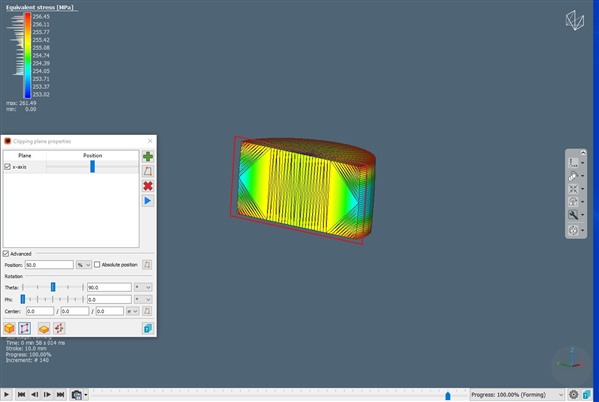
Looks like you are running a 2d axisymmetric simulation and use the "expand results" option to view the results as 3d. Clipping these results leads to terrible wrong effects and should not be supported at all. Basically we just expand the surface results.
To see the mesh, disable "expand results" using the toolbar button provided.
Or got to Extras \ Settings\ View \ Result expansion and select to expand the workpiece and the dies not by 360° but only to 270° or 90°. This way you get a 3d impression with the correct mesh shown every where.