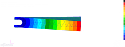
I would like to describe a rotation bearing in Patran. (Dynamic; Explicit Nonlinear) I already tried several kinds of displacements. But in all of them the solid (incl. density) either falls straight down or is fully constrained. (Please see the PDF attached) I would like the rod to be able to swing around the bearing.
MSC Nastran SOL700 is not supported anymore, so I've attached the model updated for Dytran.
To ensure large displacement effects, we use instead a nodal rigid body to define the fixing area. Then a rigid body object can define how this rigid body is constrained. In your case free in RZ. Therefore no complication between 6DOF nodes and 3DOF nodes of solids vs shells etc.
1) MSC Nastran has many SOLution sequences (SOL101, 200, 400, etc). SOL700 is the embedded explicit nonlinear solver inside MSC Nastran. In versions up to 2017 MSC Nastran SOL700 used the structural solver of LS-Dyna with the fluid and coupling solver of Dytran. Dytran itself was a creation of MSC.Dyna (which came from the opensource Dyna3D which was further developed into LS-Dyna) and MSC.Pisces, an explicit Eulerian code. Since Dytran and LS-Dyna shared the same structural roots it was natural to combine it as Dytran has been focused on fluid-structure interaction problems and LS-Dyna on highly parallel structural analysis. The thinking therefore was to have the ultimate best performer.
2) Unfortunately in 2017 LSTC, the owners of LS-Dyna stopped our agreement to use their solver as part of SOL700. Therefore from 2018 MSC Nastran will have a 'new' SOL700 that is using an all Dytran solver for explicit analysis. However Patran and SimXpert have not been updated to reflect this, so the inputs are still based on the 2017 and earlier SOL700. There is also no difference to Dytran and 2018 MSC Nastran SOL700 as they are using the same solver, some users want to stay in the Nastran environment and prefer to use SOL700.
3) That's correct - Dytran is a single solver that handles structural and/or fluid analysis. I think the menu input was just to short to allow for 'Structural and Fluids' :)
4) In Dytran gravity is seen as an environmental condition as it affects all (structure and fluid), so you will find it in the Analysis menu: Execution Control: Inertia
5) Some elements like solids only have 3 degrees of freedom (translation only), while others like shells have 6. Therefore if you link a shell node rigidly in all 6DOF to a solid node be aware that it could still rotate around the solid node as it can't constrain rotation.
6) This is just to apply the LBC marker to some point to help visualise it. This is not a requirement or have to be added to a specific point.
7) In that case you will have to. This can be done by defining a Rigid Material and setting the cg at the new location.
8) I think that was something i tried earlier and forgot to remove completely (you'll see the application region is blank). This can be deleted